Sawyer Buckminster Fuller
|
| |
| Engineering |
|
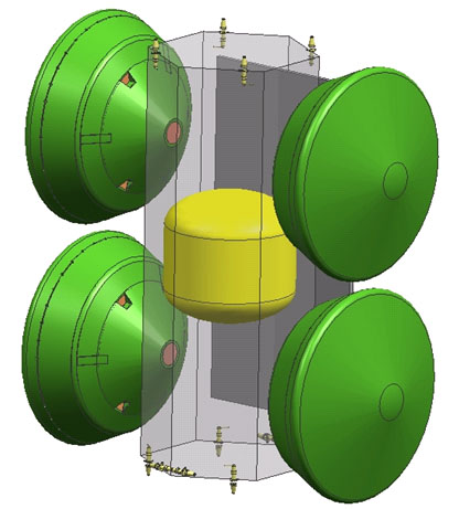 |
Mars network lander mission concept Planetary Science Summer School, Jet Propulsion Laboratory, 2004 I learned how to design a scientific mission to Mars in this summer course at JPL that showed us how they do it at NASA at JPL. Our team of students specified basic goals and shadowed JPL's Team X -- a group of engineers and scientists from across the Lab. This team works by bringing together about 20 engineers and scientists, each in a different specialty such as thermals or entry, descent, and landing, and sits them down in the same room with an automated program running on an array of workstations. Over time, interdependent mission parameters such as cost estimates, thermal limits, rocket costs, orbit mechanics, are iterated until a workable solution is found. Occasionally, the team leader calls for small meetings between specialists when it becomes clear that a mission-critical decision must be made. Our group settled on a four-lander mission to Mars to measure globe-wide seismic activity, which would help understand the makeup of Mars' interior and thus its history. At the left is an image of our design during its cruise-phase between Earth and Mars. Each of the four landers is embedded inside the aeroshell it will use brake itself as it enters Mars' atmosphere, and the yellow tank holds fuel for course correction maneuvers.
|
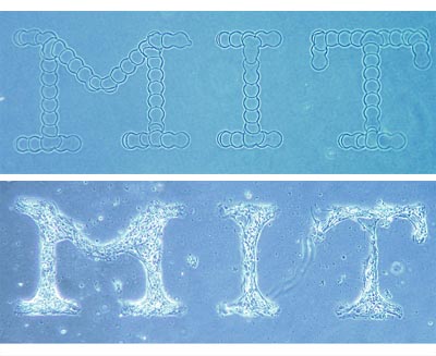 |
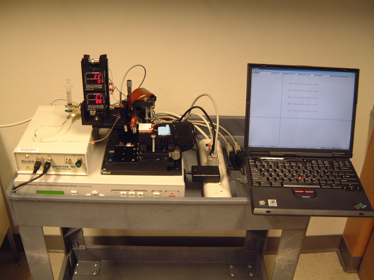
Nerve-cell-patterning ink-jet printer Advisors: Prof. Sebastian Seung and Shuguang Zhang, MIT, 2001-2003 I built this printer as part of my Master's thesis. It was designed to push the limits of ink-jet printer resolution for use in patterning nerve cells. I wrote a custom graphical interface and printer controller using Visual Basic. The printer was able to fabricate patterns of water- or solvent-based materials onto a glass coverslip, and neurons remained adhered to the pattern for over a month in culture. They showed evidence of functional synapses and spiking activity. We wanted to wire individual or small ensembles of neurons together in specific patterns so that their behavior can be more readily analyzed.
|
|
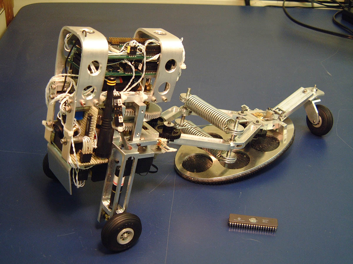
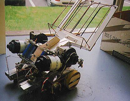
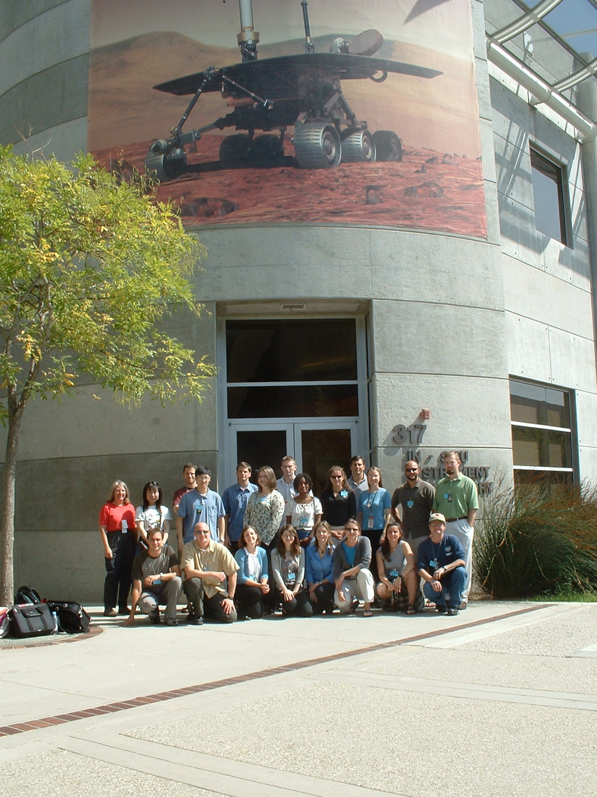
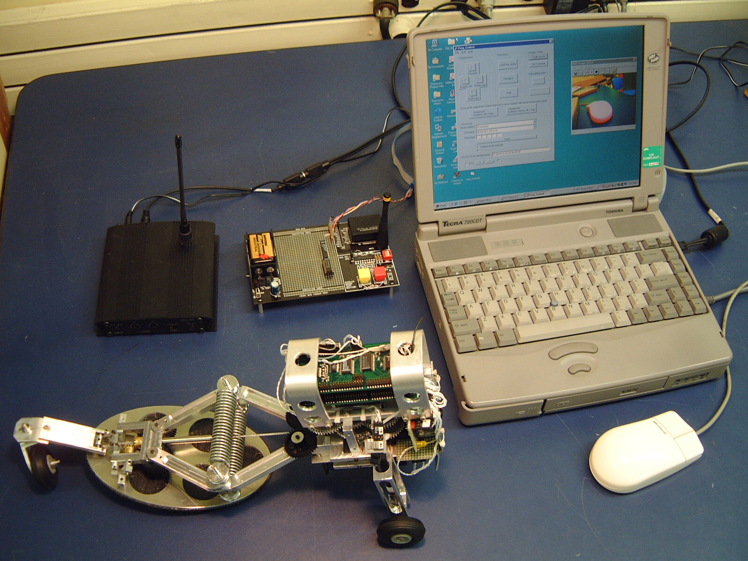
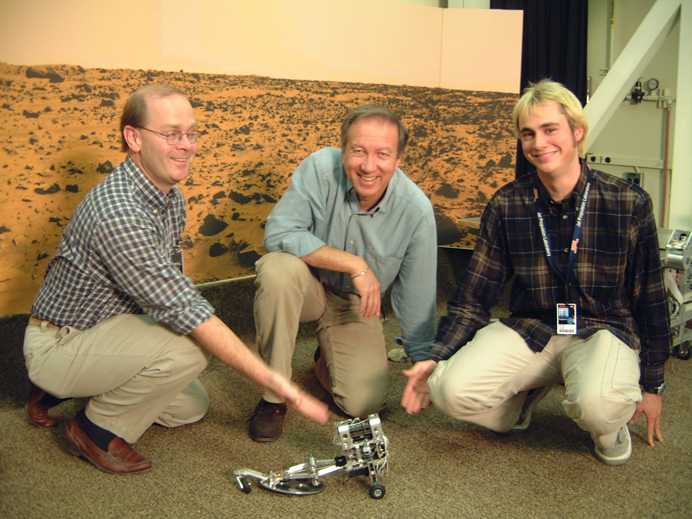
Hopping Mars rover Advisors: Prof. Paolo Fiorini and Prof. Joel Burdick, Jet Propulsion Laboratory and Caltech, 2000 The most interesting places for geologists are the most difficult to navigate for wheeled rovers: steep terrain where historic layers of sediment are exposed. The idea for this project was to construct the simplest possible rover and deploy them in droves to these hard-to-reach places with less concern for whether they would ever get out. With the capability to make big jumps, these frog-hopping rovers would be right at home in canyons and caves. I built the electronics hardware and software for this prototype. It carried dual PIC-based microcontrollers for computation, a skeleton sensor suite consisting of a wireless videocamera, and a wireless modem for dispatching high-level commands and reading back sensor information, all powered by battery. The simplicity of this rover is demonstrated by the utilization of its primary hopping motor. To hop, the motor first rotated in one direction to load a large spring between its knees. Once loaded, the motor would reverse to engage an ankle mechanism that could tilt the rover back onto its single foot to a desired hopping angle, retracting its wheels. It then reversed the motor again, releasing the spring and performing a hop (video). The command center and Joel, Paolo, and I with the hopbot.
|
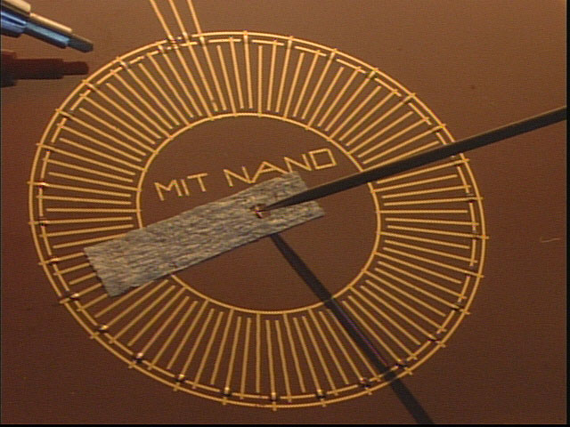 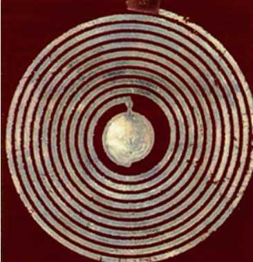 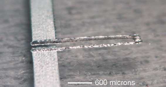 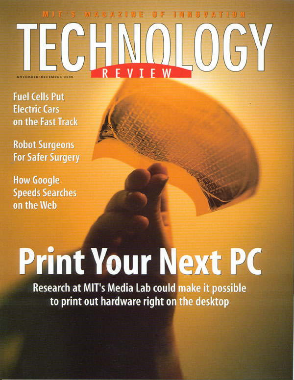 |
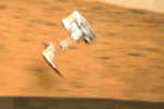
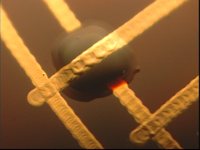
Ink-jet fabricated circuits, tags, and micro-electromechanical machines Advisor: Prof. Joseph Jacobson, MIT Media Laboratory, 1998-2000 I invented this ink-jet printer to print electrical circuits and micro-electromechanical machines (MEMS). The invention was inspired by the need for cheap printable backplane circuitry to drive "electronic paper" E-ink that was spun out of our lab and is now the core technology of the Amazon Kindle. It was also motivated by the dream of "desktop fabrication" of microchips as part of an all-purpose fab lab. Parts were fabricated by printing layers of metal nanoparticle ink and then bonding the particles together with heat. The temperature was low enough that circuits could be printed on flexible plastic, avoiding the extreme processing required by silicon microfabrication. This was the first demonstration of ink-jet printing functional active MEMS devices out of nanoparticle ink. From top left: 1. Electrostatic rotary motor using a piece of tissue paper as the rotating arm (a close-up, video). 2. Resonant inductive coil (a 1-bit radiofrequency "RFID" tag) (video). 3. Electrothermal cantilever actuator on glass built from many layers of ink (video). 4. Cover image from feature story about our work in Technology Review.
|
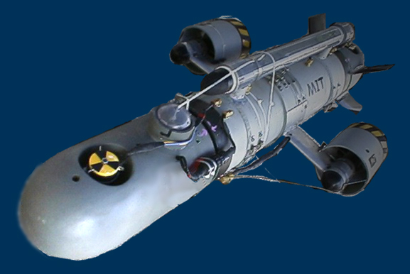 |
ORCA-1 Autonomous submarine MIT ORCA team, AUVSI autonomous underwater vechicle competition, 1998 I was on the mechanical group in the inaugural ORCA-1 submarine team.
|
 |
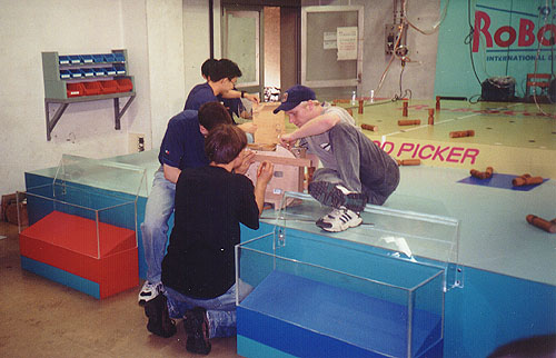
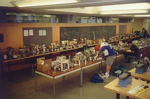
"Woodchuck" ROBOCON International Design Contest Robocon International Design Contest, Tokoyo, Japan 1997 As a follow-up contest to MIT's 2.007 contest, top competitors were invited to take part in an international design contest, held that year in Tokyo. Students from six countries around the world separated into six teams with one member from each country on each team. The contest was nationally-televised on NHK, Japan's equivalent to PBS in the USA.
|
 |
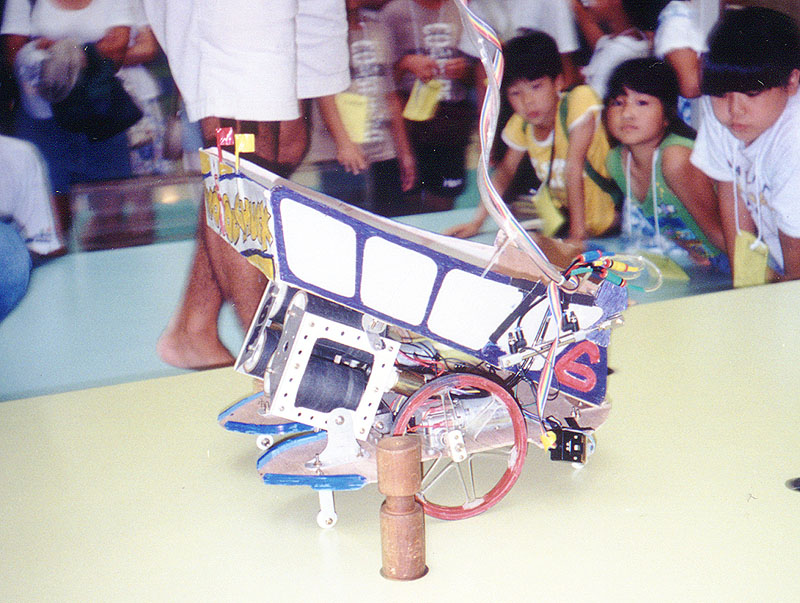
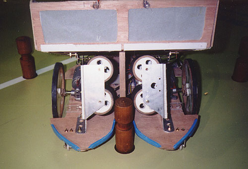
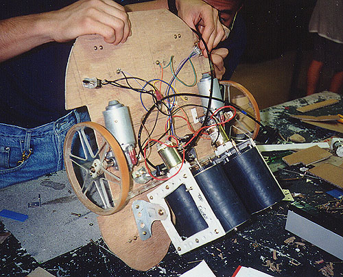
"Thwoooop", MIT 2.007 Contest MIT 2.007 Mechanical Engineering design contest, 1997 I built this robot for MIT's mechanical engineering design course, which culminates in a popular contest pitting robots against each other for points. The theme of my year's contest was "Pass the Puck," and the way points were scored was by removing various objects from your side of the table. My approach was to gather balls and fire them across the table like a tennis-ball server. I refined an idea borrowed from an earlier contest in which balls were picked up by pressing a rubber net between them, sort of like how tennis-ball baskets pick up balls. I managed to make it all the way to second place, out of a total lineup of 144 robots, using this outrageous idea.
|
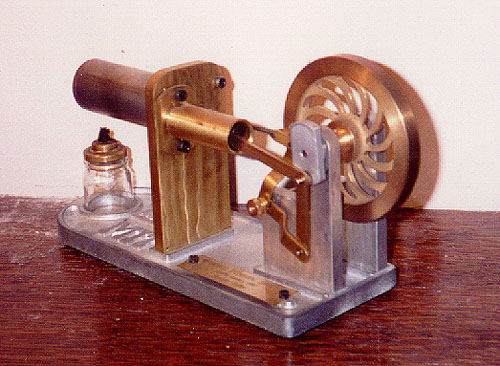 |
Stirling Engine MIT course 2.670: Mechanical Engineering tools, 1997 I built this custom-modified engine as part of a course taken by all mechanical engineering students where we learn machining and some computer modelling. It uses the stirling cycle to generate rotational power, powered by a candle on one end. In this course, students are given the opportunity to make custom modifications to their engine. I added ball bearings, a custom-machined flywheel design, and I opened up one of the air-paths through the engine.
|
|
|