Dr. Layer
1.0
An
Introduction to the Theory of Wave Propagation in Layer Media
Transfer Functions
In the following sections, transfer functions are derived for a series of successively more complicated geotechnical conditions. Although the simplest of these may only rarely be applicable to actual problems, they illustrate some of the important effects of soil deposits on ground motion characteristics without undue mathematical complexity. The more complex are capable of describing the most important aspects of ground response and are very commonly used in geotechnical earthquake engineering practice.
Uniform Undamped Soil on Rigid RockFirst, consider a uniform layer of isotropic, linear elastic
soil overlying rigid bedrock as shown in Figure 1. Harmonic horizontal
motion of the bedrock will produce vertically propagating shear waves
in the overlying soil. The resulting horizontal displacement can be expressed
as:
|
|
(1)
|
where w is the circular frequency of ground shaking, k
the wave number (=w/ns) and A and B the amplitudes of waves traveling in
the z (upward) and +z (downward) directions, respectively. At the free
surface (z=0), the shear stress, and consequently the shear strain, must
vanish; that is,
|
|
(2)
|
Substituting (1) into (2) and differentiating yields
|
|
(3)
|
which is satisfied (nontrivially) when A=B. The displacement
can then be expressed as
|
|
(4)
|
which describes a standing wave of amplitude 2A cos(kz).
The standing wave is produced by the constructive interference of the
upward and downward traveling waves and has a fixed shape with respect
to depth. Equation (4) can be used to define a transfer function that
describes the ratio of displacement amplitudes at any two points in the
soil layer. Choosing these two points to be the top and bottom of the
soil layer gives the transfer function
|
|
(5)
|
The modulus for the transfer function
is the amplification function
|
|
(6)
|
which indicates that the surface displacement is always at least as large as the bedrock displacement (since the denominator can never be greater than 1) and, at certain frequencies, is much larger. Thus |F1(w)| is the ratio of the free surface motion amplitude to the bedrock motion amplitude (or, since the bedrock is rigid in this case, the bedrock outcropping motion). As wH/ns approaches p/2+np, the denominator of equation (6) approaches zero, which implies that infinite amplification, or resonance, will occur (Figure ()). Even this very simple model illustrates that the response of a soil deposit is highly dependent upon the frequency of the base motion, and that the frequencies at which strong amplification occurs depend on the geometry (thickness) and material properties (s-wave velocity) of the soil layer.
Uniform, Damped Soil on Rigid RockObviously, the type of unbounded amplification predicted
by the previous analysis cannot physically occur. The previous analysis
assumed no dissipation of energy, or damping, in the soil. Since damping
is present in all materials, more realistic results can be obtained by
repeating the analysis with damping. Assuming the soil to have the shearing
characteristics of a Kelvin-Voigt solid, the wave equation can be written
as
|
|
(7)
|
As shown in the previous section, the solution to this
wave equation is of the form
|
|
(8)
|
where k* is a complex wave number
with real part k1 and imaginary part k2. Repeating
the previous algebraic manipulations with the complex wave number, the
transfer function for the case of damped soil over rigid rock can be expressed
as
|
|
(9)
|
Since the frequency-independent
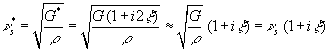
complex shear modulus is given by G*=G(1+i2x), the complex shear velocity can be expressed
as
 |
(10)
|
for small x.
Then the complex wave number can be written, again for small x,
as
|
|
(11)
|
and finally, the trasfer function
as
|
|
(12)
|
Using the identity |cos(x+iy)|
= sqrt[cos2(x)+sinh2(y)], the amplification function
can be expressed as
|
|
(13)
|
Since sinh2y ~ y2 for small y,
the amplification function can be simplified to
|
|
(14)
|
For small damping ratios, equation (14) indicates that amplification by a damped soil layer also varies with frequency. The amplification will reach a local maximum whenever kH~p/2+np but will never reach a value of infinity since (for x>0) the denominator will always be greater than zero. The frequencies that correspond to the local maxima are the natural frequencies of the soil deposit. The variation of amplification factor with frequency is shown for different levels of damping in Figure (). This amplification factor is also equal to the ratio of the free surface motion amplitude to the bedrock (or bedrock outcropping) motion amplitude. Comparing Figures () and () shows that damping affects the response at high frequencies more than at lower frequencies.
The nth natural frequency of the
soil deposit is given by
|
|
(15)
|
Since the peak amplification factor
decreases with increasing natural frequency, the greatest amplification
factor will occur approximately at the lowest natural frequency, also
known as the fundamental frequency
|
|
(16)
|
The period of vibration corresponding
to the fundamental frequency is called the characteristic site period,
|
|
(17)
|
The characteristic site period, which depends on the thickness and shear wave velocity of the soil, provides a very useful indication of the period of vibration at which the most significant amplification can be expected.
Uniform Damped Soil on Elastic Rock
References
Kramer, S. L. (1996), "Geotechnical Enarthquake Engineering", Prentice Hall.
Last
Updated:
11/21/00
Contact us at: parduino@u.washington.edu