Dr. Layer
1.0
An
Introduction to the Theory of Wave Propagation in Layer Media
Material Boundary in an
Elastic Half-space
Consider a harmonic stress wave traveling along an elastic half-space in the +z direction and approaching an interface between two different materials, as shown in Figure 1. Since the wave is traveling towards the interface, it will be referred as incident wave. Since it is traveling in material 1, its wave-length will be l1=2p/k1, and it can therefore be described by
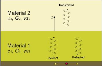
Figure 1. One Dimensional Wave Propagation at Material Interface
|
|
(1)
|
 |
(2a) (2b) |
Assuming that the displacements
associated with each of these waves are of the same harmonic form as the
stresses that cause them; that is
 |
(3a) (3b) (3c) |
 |
(4a) (4b) (4c) |
 |
(5a) (5b) (5c) |
At the interface, both compatibility
of displacements and continuity of stresses must be satisfied. The former
requires that
|
|
(6)
|
|
|
(7)
|
|
|
(8a) (8b) |
|
|
(9)
|
|
|
(10)
|
|
|
(11)
|
|
|
(12)
|
|
|
(13)
|
After evaluating the effect
of the interface on the displacement amplitudes of the reflected and transmitted
waves, its effect on stress amplitudes can be investigated. From equations
(5)
|
|
(14a)
|
|
|
(14b)
|
|
|
(14c)
|
|
|
(15)
|
|
|
(16)
|
Interesting Impedance Ratio Phenomena
The importance of the impedance ratio in determining the
nature of the reflection and transmission at interfaces can clearly be
seen. Equations (12), (13), (15), and (16) indicate that fundamentally
different types of behavior occur when the impedance ratio is less than
or greater than 1. When the impedance ratio is less than 1, an incident
wave can thought of as approaching a softer material. For this case,
the reflected wave will have a smaller stress amplitude than the incident
wave and its sign will be reversed. If the impedance ratio is greater
than 1, the incident wave is approaching a stiffer material in which
the stress amplitude of the transmitted wave will be greater than that
of the incident wave and the stress amplitude of the reflected wave will
be less than, but of the same sign, as that of the incident wave. The
displacements amplitudes are also affected by the impedance ratio. The
relative stress and displacement amplitudes of reflected and transmitted
waves at boundaries with several different impedance ratios are illustrated
in Table 1.
| Impedance Ratio |
Displacement Amplitudes
|
Stress Amplitudes
|
||||
|
az |
Incident |
Reflected
|
Transmitted
|
Incident
|
Reflected
|
Transmitted
|
|
0 |
Ai
|
Ai
|
2Ai
|
si
|
-si
|
0
|
|
1/4 |
Ai
|
3Ai/5
|
8Ai/5
|
si
|
-3si/5
|
2si/5
|
|
1/2 |
Ai
|
Ai/3
|
4Ai/3
|
si
|
-si/3
|
2si/3
|
|
1 |
Ai
|
0
|
Ai
|
si
|
0
|
si
|
|
2 |
Ai
|
-Ai/3
|
2Ai/3
|
si
|
si/3
|
4si/3
|
|
4 |
Ai
|
-3Ai/5
|
2Ai/5
|
si
|
3si/5
|
8si/5
|
|
¥ |
Ai
|
-Ai
|
0
|
si
|
si
|
2si
|
The case of az=1, in which the impedances on each side of the boundary are equal, is also of interest. Equations (12), (13), (15), and (16) indicate that no reflected wave is produced and that the transmitted wave has, as expected, the same amplitude and polarity as the incident wave. In other words, all of the elastic energy of the wave crosses the boundary unchanged and travels away, never to return. Another way of looking at a boundary with an impedance ratio of unity is as a boundary between two identical semi-infinite media. A harmonic wave traveling in the positive z-direction (Figure 2-A) would impose an axial force [(see equation()] on the boundary
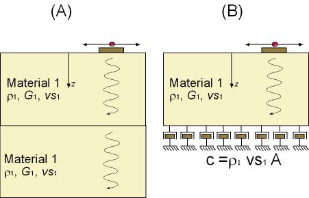
Figure 2. (A)Harmonic shear
wave traveling along two connected soil layers; (B) Soil layer connected
to a dashpot
|
|
(19)
|
References
Kramer, S. L. (1996), "Geotechnical Enarthquake Engineering", Prentice Hall.
Last
Updated:
11/21/00
Contact us at: parduino@u.washington.edu