
Welcome to The UW Shoulder Site @ uwshoulder.com
Please note that information on this site was NOT authored by Dr. Frederic A Matsen III and has not been proofread or intended for general public use. Information was intended for internal use only and is a compilation for random notes and resources.
If you are looking for medical information about the treatment of shoulders, please visit shoulderarthritis.blogspot.com for an index of the many blog entries by Dr. Frederick A Matsen III.
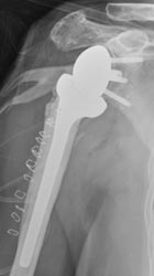
Delta Xtend Technique Guide
|
|
Equipment Needed
Setup
Place templated x-rays, clinic notes and progress note on x-ray box.
.png)
Prefill-out orders and setup pt in a beach chair position. The operative arm should be able to hang off bed as shown below.
.png)
.png)
You should circumferentially wrap cloth tape around the patient's chest and table to prevent pulling the patient off of the table during the surgery. This taping is in addition to use of the patient's normal safety belt.
You should NOT be using the old RA table of Beachchair attachment for this case. If for some reason you are using these systems (such as to help with fluoro) DO NOT REMOVE THE SHOULDER SUPPORT! Removing the shoulder support under the operative side may seem like a good idea but the patient will eventually migrate off of the table.
The anesthesia team and ortho team should work together to tape the patient's head down. You may need to use a clipboard to support the head (if using the RA table or Beachchair attachment). We do not secure the head in a brace as shown above.
A 1010 drape should be secured around the patients neck and the free end secured to the tape holding the patients head. Securing the free end prevents it from falling onto the sterile field when prepping.
ROM of the operative shoulder should be measured and recorded on the board in the following order: FE, ER, IRA, ERA, CBA.
Double Prep
A member from the ortho team needs to wash and gown and prep the patient's operative side. ChloraPrep is the prep of choice.
Prep from the middle of the chest out to the wrist, followed by armpit, followed by wrist, hand and fingers. This should be done a total of three times.
The first drape is setup under the patients head, operative arm and over the patient's waist. If possible, the drape should be tucked under the patient's belt. This draping is done by the nursing staff or other member of ortho team.
The first set of gloves are removed and the second prep is performed in the same manner as the first.
The second drape is setup over the first in the same manner.
Draping
After the two initial drapes are placed under the head shoulder and over the waist, one drape is place over the chest and feet. This should go from the patient's armpit to the patient's neck.
Another drape is placed over the head and overlaps across the chest drape.
The three corners where these drapes come together are stapled. There is no need to staple the drapes directly to the patient.
The arm should be covered with a stockinet and a dry sponge placed in the patient's axilla.
|
A clear adhesive plastic is used to cover all exposed skin.
At some point a timeout will be performed by the circulating nurse, attending and anesthesia team. The room should otherwise be free from any talking or other distracting noises during the timeout. |
|
Approach Prior to making an incision, a formal timeout will be performed by the attending circulating nurse, and anesthesia team. The room should otherwise be free from any talking or other distracting noises during the timeout.
Make your incision from the coracoid down, 10 cm or so. |
|
A scalpel should be used until the surgeon reaches muscle. Mayo scissors are then used to dissect through fascia to locate the cephalic vein and deltopectoral interval. |
The deltopectoral interval should be blunt dissected with the surgeon's index finger, taking the vein laterally. Make an effort to preserve as much deltoid muscle as possible.
The motion interface under the deltoid and pectoralis should be freed up and the conjoined tendon located.
Remember to free up the conjoined tendon on its lateral side so that the tendon can be retracted medially. Incising into anything medial to the lateral border of the conjoined tendon can result in musculocutaneous nerve injury.
When the lateral border of the conjoined is freed up, use a medium Richardson retractor to pull the conjoined medially. Use a Balfour to expose the rotator cuff /superior humerus.
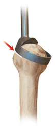
Bursa should be removed to better visualize the subscapularis. Identify the long head bicep tendon and plan to free the subscapularis as close to and medial to the biceps without cutting it. If surgery is for rotator cuff arthropathy, it is likely that the long head biceps will not be in its anatomical position.
Free the subscapularis from the humerus and tag stitch it twice. Once it has been sufficiently freed, the humeral head should easily dislocate.
|
Humeral Cut
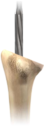
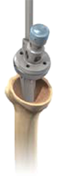
Use a high speed burr to make your pilot hole.
Use a curette to find the humeral shaft. Make sure that one hand is used to hold the elbow to help you correctly angle your curette. |
The manufacture recommends humeral reaming at this point, but this can be done later if the surgeon chooses to use the old Delta humeral cutting instead of the new complex cutting system.
|
|
 Note: some surgeons may wish to start their cut with the cutting guide in place. With this method, the cut is started and the cutting guide is later removed to allow the blade to complete its cut. |
Use a saw to carefully cut the humeral head. The trigger on the saw is configured for variable speed. Careful trigger control will allow you to control the speed of your saw and allow for a more controlled and precise cut.
.png) The fancy cut protector shown
left may be used at the discretion of the surgeon. This device may
obstruct visualization of the glenoid but it allows
for the DePuy Xtend forked Homan to lever on the humerus with less
chance of
crushing it. The fancy cut protector shown
left may be used at the discretion of the surgeon. This device may
obstruct visualization of the glenoid but it allows
for the DePuy Xtend forked Homan to lever on the humerus with less
chance of
crushing it. |
Glenoid
.png) Use Homan and double Homan retractors to expose the glenoid. Use Homan and double Homan retractors to expose the glenoid. |
.png) Determine where the spine of the scapula is and stick the double Homan
retractor there to mark your spot. Determine where the spine of the scapula is and stick the double Homan
retractor there to mark your spot. |
.png) .png) Assemble the metaglene positioner by inserting and threading the internal rod
into the positioner handle. Do so by inserting the hex head tip of the
handle in the corresponding plate hole (right or left depending on the shoulder
being operated upon) and lock the assembly by tightening the internal rod. Assemble the metaglene positioner by inserting and threading the internal rod
into the positioner handle. Do so by inserting the hex head tip of the
handle in the corresponding plate hole (right or left depending on the shoulder
being operated upon) and lock the assembly by tightening the internal rod.
For right shoulders, the positioner handle should be placed in the 2 o'clock hole.
For left shoulders, the postioner handle should be placed in the 10 o'clock hole. |
.png) Position the plate as low as possible so that its border follows the inferior
edge of the glenoid. Position the plate as low as possible so that its border follows the inferior
edge of the glenoid.
The guide plate should be held perpendicular to the plane of the glenoid face. Make sure that the proximal handle of the instrument is not tilted superiorly. The guide pin should be inserted either perpendicularly to the glenoid face or with the distal tip of the guide pin in a slightly superior direction. This ensures that the glenosphere will either be perpendicular to the plane of the glenoid face or have a slight inferior tilt which may reduce the risk of scapular notching. |
|
|
.png) .png) Remove the metaglene positioner, leaving the guide pin in place. |
|
Be careful not to over ream and to preserve the subchondral bone. |
.png) Ream the superior glenoid bone by hand, using the manual 42 mm glenoid reamer.
This step is necessary to avoid any potential conflict
between the glenosphere and the superior area of the glenoid bone. Manual
reaming should be carried out until the central part of the manual reamer is in
full contact with the curved central glenoid surface. Ream the superior glenoid bone by hand, using the manual 42 mm glenoid reamer.
This step is necessary to avoid any potential conflict
between the glenosphere and the superior area of the glenoid bone. Manual
reaming should be carried out until the central part of the manual reamer is in
full contact with the curved central glenoid surface.
Use the manual glenoid reamer to ream the glenoid anteriorly, posteriorly and inferiorly if necessary. A smooth surface without any remaining cartilage should be obtained. |
.png) .png) Check the adequacy of the reaming by applying the glenoid reaming level checker on the glenoid surface. No space (except if due to bone erosion) should be seen between the instrument and the glenoid surface. |
|
|
|
Remove the stop drill and the central guide pin. |
|
|
.png) .png) Place the metaglene on the glenoid bone and ensure that the metaglene is fully seated. Apply bone graft if necessary to help fill surface irregularities between the metaglene and the glenoid bone. Rotate the metaglene so that the inferior screw can be aimed toward the scapular neck. The vertical metaglene marking should be aligned with the scapular neck inferiorly and with the base of the coracoid process superiorly (long axis of the glenoid bone). The metaglene peg is 0.6 mm larger in diameter than the drill to enable a press fit. With a mallet, gently impact in the proper orientation for inferior screw placement and then remove the metaglene holder. |
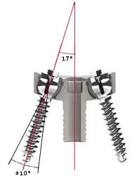 Locking metaglene screws allow an angulation of ± 10 degrees around the
optimal 17° screw positioning recommended by
Professor Grammont. Locking metaglene screws allow an angulation of ± 10 degrees around the
optimal 17° screw positioning recommended by
Professor Grammont. |
.png) .png) Place the 2.5 mm drill guide in the metaglene inferior hole. The drill guide can be angled to ± 10 degrees but should always be seated fully in the metaglene hole. Palpate the scapular neck and aim into good bone. Using the 2.5 mm drill bit, start drilling through the subchondral bone to aproximately 10 to 12 mm deep. Then stop drilling and push gently on the drill bit to make sure that the drill is contained in the bone. Redirect and re-drill if uncontained. When a satisfactory drilling direction has been obtained, drill and push until the cortex is perforated. |
.png) The goal is to have a sufficiently long screw inferiorly, usually 36 mm or
more. The length of the screw is indicated on the drill bit by laser markings.
The screw depth gauge can also be used to assess optimal screw length. The goal is to have a sufficiently long screw inferiorly, usually 36 mm or
more. The length of the screw is indicated on the drill bit by laser markings.
The screw depth gauge can also be used to assess optimal screw length. |
.png) .png) Use of the guide pin is optional and may or may not be used. If used, insert the 1.2 mm guide pin through the drill guide and then remove the drill guide. Slide the locking screw of the appropriate length onto the guide pin. Check that the internal tightening screw is unlocked (It should rotate freely). Slide the locking screwdriver body on the guide pin and insert the tip into the 4 slots on the screw.
The manufacture does not recommend use of the internal screwdriver rod at this stage but it is difficult to control the screw without locking it to the driver. You can lock the screw to the drive by sliding down the screwdriver sleeve completely to protect the screw head and tightening the internal screwdriver rod to lock it on the sleeve. The internal screwdriver rod should be removed prior to handing tool to the surgeon. |
.png) Tighten the screw to compress the plate. Tighten the screw to compress the plate. |
.png) .png) If used, remove the screw guide pin before final tightening to avoid stripping, making sure that the internal locking screw stays in place. |
.png) Repeat the same steps for the superior locking screw. Repeat the same steps for the superior locking screw.
Drill the hole for the superior locking screw anticipating exit through the far cortex. The superior screw should be directed at the base of the coracoid process and should have an anterior orientation to avoid the suprascapular nerve. To obtain optimal compression of the metaglene plate on bone, alternate tightening of the superior and inferior locking screws. |
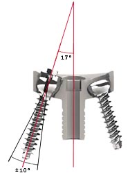 The surgeon may use locking or non-locking screws in the anterior or
posterior holes. Both types of screws will allow an angulation of up to ± 10
degrees, but not in a direction convergent to the central peg axis to avoid
conflict with the central peg. The surgeon may use locking or non-locking screws in the anterior or
posterior holes. Both types of screws will allow an angulation of up to ± 10
degrees, but not in a direction convergent to the central peg axis to avoid
conflict with the central peg.
Use the 2.5 mm drill bit with the drill guide to set the most appropriate angle for ensuring that each screw is located in reliable bone stock. The preferred position is usually chosen by palpating the anterior and posterior aspects of the scapula as well as examining the X-rays. |
|
Drill in the direction of the central glenoid vault in an attempt to maximize the anterior and posterior compression screw lengths, in a direction ideally parallel to or divergent from the central peg. Screws can be angled in towards the central peg for patients with narrow glenoid necks. |
|
|
.png) The
surgeon may wish to use a guide pin to align the screw, or simply
remember the angle of the drill prior to screwing in your screw. The
surgeon may wish to use a guide pin to align the screw, or simply
remember the angle of the drill prior to screwing in your screw.
Slide the corresponding screws onto the guide pin, if used, and tighten using the 3.5 mm cannulated hex screwdriver for non-locking screws (white handled driver) or the locking screwdriver for locking screws. Follow the same procedure for the posterior screw, then alternately tighten both screws until they are fully tightened. |
If you choose to lock your screws onto the driver, you will need to loosen the locking inner screws of each locking screw and retighten the outer screws.
.png) Proceed with locking all variable angle screws used. Place the locking
screwdriver main body in the head of the inferior screw. Make sure that
the screwdriver sleeve is in its upper position and not in contact with the screw
head. Slide the locking screwdriver internal rod into the main body. The
tip of the internal rod will make contact with the screw head. Tighten it fully,
locking the screw in place by expanding its head. Proceed with locking all variable angle screws used. Place the locking
screwdriver main body in the head of the inferior screw. Make sure that
the screwdriver sleeve is in its upper position and not in contact with the screw
head. Slide the locking screwdriver internal rod into the main body. The
tip of the internal rod will make contact with the screw head. Tighten it fully,
locking the screw in place by expanding its head.
Repeat the same steps to secure the superior locking screw and anterior or posterior screws if variable angle screws have been used.
|
Humeral Component
|
|
 Continue to ream sequentially until the reamer just begins to bite on the
cortical bone of the intramedullary canal of the humerus. CTA bone is
often on the soft side so make a note of not over reaming. Continue to ream sequentially until the reamer just begins to bite on the
cortical bone of the intramedullary canal of the humerus. CTA bone is
often on the soft side so make a note of not over reaming. |
.png)
|
|
|
|
|
.png) Unscrew the upper round handle of the holder and remove the holder, leaving the
proximal reamerguide in place. Unscrew the upper round handle of the holder and remove the holder, leaving the
proximal reamerguide in place.
|
.png) .png) Unless
you are using a size 8 stem, which only comes with a number 1 head. The monobloc implant size should be chosen to match the initial distal
reaming diameter. Choose the most appropriate epiphysis size by
placing a monobloc implant sizer disk in size 1 (Yellow) or 2 (Blue) on the proximal reaming
guide. The most appropriate size will be the sizer disc that provides the best
possible coverage of the bone resection surface. The size chosen,
epiphysis size 1 or 2, will determine proximal reamer and final implant sizes. Unless
you are using a size 8 stem, which only comes with a number 1 head. The monobloc implant size should be chosen to match the initial distal
reaming diameter. Choose the most appropriate epiphysis size by
placing a monobloc implant sizer disk in size 1 (Yellow) or 2 (Blue) on the proximal reaming
guide. The most appropriate size will be the sizer disc that provides the best
possible coverage of the bone resection surface. The size chosen,
epiphysis size 1 or 2, will determine proximal reamer and final implant sizes. |
Remove the sizer disk.
.png) Select the appropriate proximal reamer for the monobloc implant, size 1 or 2,
from the results of the previous trials. Ream the metaphysis using a hand
reamer. The manufacture recommends power reaming but CTA patients often
have soft bone and power may be overkill and dangerous. Select the appropriate proximal reamer for the monobloc implant, size 1 or 2,
from the results of the previous trials. Ream the metaphysis using a hand
reamer. The manufacture recommends power reaming but CTA patients often
have soft bone and power may be overkill and dangerous. |
|
|
Complete reaming is achieved when the external reamer flange is in full and complete contact withthe bone resection surface. When the proximal reaming has been completed, remove the reaming guide using the reaming guide holder. |
Trialing
Select the appropriate trial humeral implant. For example, if the initial distal reaming was carried out using the 12 mm reamer and proximal reaming was carried out using the size 1 proximal reamer, select monobloc humeral trial epiphysis number 1 with diameter 12 mm.
 Mount the trial implant on the humeral implant driver and drive it down the
intramedullary canal. The implant orientation should be checked by making
sure that the arm is held at 0 degrees of retroversion and face of the
prosthesis is lined up with the axis of the body. Mount the trial implant on the humeral implant driver and drive it down the
intramedullary canal. The implant orientation should be checked by making
sure that the arm is held at 0 degrees of retroversion and face of the
prosthesis is lined up with the axis of the body. |
.png) With everything aligned properly, drive the trial implant down. Impact
the trial implant by gently tapping the implant driver handle and remove the
driver, leaving the trial implant in place. The driver is detached by pushing on
the blue button. With everything aligned properly, drive the trial implant down. Impact
the trial implant by gently tapping the implant driver handle and remove the
driver, leaving the trial implant in place. The driver is detached by pushing on
the blue button. |
The glenosphere implants are available in two diameters, 38 mm and 42 mm, and are either standard or eccentric spheres. We generally use a 38mm standard sphere.
.png) Fit the appropriate trial glenosphere to the the metaglene using the
metaglene holder if necessary. Fit the appropriate trial glenosphere to the the metaglene using the
metaglene holder if necessary.
The surgeon may wish to use the cup impactor to set the trial. |
.png) For eccentric glenospheres, the vertical laser mark on the trial glenosphere
should be aligned with the base of the coracoid superiorly and the scapular neck
inferiorly. The arrow indicates the position of the eccentricity and
should be positioned inferiorly, aligned with the scapular neck. For eccentric glenospheres, the vertical laser mark on the trial glenosphere
should be aligned with the base of the coracoid superiorly and the scapular neck
inferiorly. The arrow indicates the position of the eccentricity and
should be positioned inferiorly, aligned with the scapular neck.
The surgeon has the option of trialing the eccentric head in a direction other than directly inferior, but may create a situation where glenoid notching will become a larger concern later on. |
.png) An overlap of 3 to 5 mm is recommended by the manufacture to avoid conflict
with the scapular neck. Depending on the shape of the scapular neck, this
overlap can be achieved by using a standard metaglene just by lowering the
metaglene. The largest 42mm glenosphere is recommended by the manufacture
if the size of the joint (allows to increase both the overlap and the range of
motion). The eccentric glenospheres are recommended by the manufactures for more
transverse scapular necks. We will generally use a 38mm gleonsphere. An overlap of 3 to 5 mm is recommended by the manufacture to avoid conflict
with the scapular neck. Depending on the shape of the scapular neck, this
overlap can be achieved by using a standard metaglene just by lowering the
metaglene. The largest 42mm glenosphere is recommended by the manufacture
if the size of the joint (allows to increase both the overlap and the range of
motion). The eccentric glenospheres are recommended by the manufactures for more
transverse scapular necks. We will generally use a 38mm gleonsphere. |
.png) Place the humeral trial cup (38 or 42 mm depending on the glenosphere size),
with +3 mm of lateral offset, in the trial epiphysis. The shoulder should
then be reduced with longitudinal traction and assessed for a full range of
motion. Place the humeral trial cup (38 or 42 mm depending on the glenosphere size),
with +3 mm of lateral offset, in the trial epiphysis. The shoulder should
then be reduced with longitudinal traction and assessed for a full range of
motion. |
.png)
Joint tensioning and stability assessment should be performed with particular care, using the following manufacture's guidelines:
If instability can be demonstrated, it is critical to identify the cause and develop a solution to the problem. Make sure that the implants have been positioned correctly with respect to the bone and to each other. Overcome any conflicts between the proximal humeral component and soft tissues or osseous structures that surround the glenosphere (e.g. non-union of the greater tuberosity) by excision of the conflicting elements. Inadequate tensioning may be overcome using:
If unable to reduce the joint, the options include additional soft tissue releases and lowering the level of humeral resection. When the trials are satisfactory, the trial glenosphere should be removed using the extraction T-Handle so that final implant fixation can be performed.
Depending on space constraints, either the glenoid or humeral components can be secured next.
Glenoid Component Emplacement
.png) Insert the 1.5 mm guide pin through the central hole of the metaglene.
Note - this is not the same pin used earlier to guide glenoid reaming. Insert the 1.5 mm guide pin through the central hole of the metaglene.
Note - this is not the same pin used earlier to guide glenoid reaming.
Engage the 3.5 mm cannulated hex screwdriver in the final glenosphere. Slide the glenosphere on the 1.5 mm guide pin until it is in contact with the metaglene. Proper alignment between the glenosphere and metaglene is absolutely essential to avoid cross threading between the components.
Make sure that there isn't any soft tissue that may become trapped between the metaglene and glenoid sphere. |
|
|
.png) The arrow marked on the orientation guide should be aligned
with the base of the coracoid process to position the eccentricity correctly.
Maintain the orientation guide in the required position and screw the
glenosphere into place using the screwdriver until the glenoid bearing closes on
the taper of the metaglene. The arrow marked on the orientation guide should be aligned
with the base of the coracoid process to position the eccentricity correctly.
Maintain the orientation guide in the required position and screw the
glenosphere into place using the screwdriver until the glenoid bearing closes on
the taper of the metaglene. |
If the glenosphere seems difficult to thread onto the metaglene, do not force engagement but re-align the components. If necessary, remove the inferior retractor or improve the capsular release. It is also important to check that there is no soft tissue between the metaglene and glenosphere.
When accurate thread engagement is obtained and after a few turns, remove the guide pin to avoid stripping in the screwdriver.
Tighten until the scapula begins to rotate slightly in a clockwise direction, meaning that the glenoid bearing is closing on the taper of the metaglene.
.png) Gently tap on the glenosphere with the glenosphere impactor a minimum of three
times. Tighten the glenosphere central screw
again. Care should be taken to ensure that the glenoid bearing is fully
locked onto the metaglene. The gentle hammering procedure and screw
tightening can be repeated, if necessary, until the screw is fully tightened. Gently tap on the glenosphere with the glenosphere impactor a minimum of three
times. Tighten the glenosphere central screw
again. Care should be taken to ensure that the glenoid bearing is fully
locked onto the metaglene. The gentle hammering procedure and screw
tightening can be repeated, if necessary, until the screw is fully tightened. |
Humeral Component Cementing
Remove the trial cups and trial implants using the humeral implant driver. Select the appropriate final monobloc humeral implant corresponding to the trial implant.
Determine the trial size of the cement restrictor and gauge the implantation depth. Check that the trial restrictor is firmly seated in the canal, then remove trial.
.png) Use pulsatile lavage and a nylon brush to clear the humeral canal of debris
and to open the interstices of the bone ready for the cement. Place the
definitive cement restrictor at the appropriate depth and check that it is
firmly seated in the canal. Use pulsatile lavage and a nylon brush to clear the humeral canal of debris
and to open the interstices of the bone ready for the cement. Place the
definitive cement restrictor at the appropriate depth and check that it is
firmly seated in the canal. |
If you have a subscapularis to repair, drill and fill 6 number 2 Tevdex suture through the proximal humerus near the lesser tuberosity to enable secure reattachment of the subscapularis (if possible). You may wish to avoid re-attachment if unable to externally rotate the humerus to zero degrees.
Irrigate the canal, during a secondary cleaning, using pulsatile lavage to remove loose bone remnants and marrow. Some surgeons may wish to insert a one-inch gauze pre-soaked in an epinephrine (1:1,000,000 solution) or hydrogen peroxide solution to aid haemostasis and the drying of the humeral canal.
.png) Cement in the humeral implant as directed. We use 1.5 packs of Simplex
with 2 grams of Vancomycin. Cement in the humeral implant as directed. We use 1.5 packs of Simplex
with 2 grams of Vancomycin. |
|
Introduce the final implant in 0 degrees of retroversion in line with the
long axis of the humerus, using the humeral implant driver. |
|
Excess cement will extrude from the canal and should be removed before curing
is complete. Remove the driver by pressing on the blue button.
Inspect the exposed portion of the humeral component for cement and remove as
necessary. |
Place pressure on the component with your thumb until the cement is fully polymerized to avoid micromotion that could cause crack propagation. Cement hardening takes about 10 minutes in the laminar airflow room and can be check by tapping on a test piece of cement.
Irrigate the wound thoroughly. Place the trial articular surface and reduce the joint. Confirm stability and dislocate the humerus.
.png) Impact the final humeral cup using the cup impactor. When a humeral spacer is
needed, impact it first on the epiphysis and then impact the final cup on it. Impact the final humeral cup using the cup impactor. When a humeral spacer is
needed, impact it first on the epiphysis and then impact the final cup on it. |
Note: All junction surfaces between the implant components should be clean and free of any tissue before impaction. Reduce the joint and carry out a final assessment of joint stability and range of motion.
Reduce the joint and carry out a final assessment of joint stability and range of motion.
Closing
Secure the subscapularis if indicated and assess ER ROM.
Close the delta-pectoral interval loosely. Emplace a drain over deltoid and exit skin a good 7.5cm or more away from incision site. Use staples to close the wound.
Postop
If iodine was used to prep the patient, this should be removed with alcohol immediately after dressing the incision site.
No CPM
Place Pt in sling
For PT - Axillary care and hand to mouth exercises.
Immediately post op, do a Grashey AP and Axillary view xray of the operative shoulder.
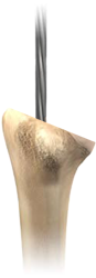
.png) The primary surgeon will mark the coracoid and a line from the coracoid down the deltopectoral interval. This interval can and should be palpated prior to marking.
The primary surgeon will mark the coracoid and a line from the coracoid down the deltopectoral interval. This interval can and should be palpated prior to marking..png)
 After incision through the dermis, two interposing
Gelpi retractors should be
used to separate the two skin edges and to pull them away from the muscle bed.
After incision through the dermis, two interposing
Gelpi retractors should be
used to separate the two skin edges and to pull them away from the muscle bed..png) Identify the midline of the humerus and mark the humeral head so that it is
centered over the humeral shaft. A common mistake is to mark the humerus
too anatomically anterior and medial.
Identify the midline of the humerus and mark the humeral head so that it is
centered over the humeral shaft. A common mistake is to mark the humerus
too anatomically anterior and medial..png) Place
the 2.5 mm metaglene central guide pin in the plate is central hole and
drill it through the far cortex using a Pin Driver.
Place
the 2.5 mm metaglene central guide pin in the plate is central hole and
drill it through the far cortex using a Pin Driver..png) Slide the 27 mm glenoid resurfacing reamer onto the central guide pin and
ream manually. Use the metaglene reamer carefully to avoid any inadvertent
fracturing of the glenoid, especially if the glenoid is sclerotic. The
reamer is also power compatible, but CTA glenoids often are too soft for power.
This reamer prepares a smooth curved surface with the same diameter as the
metaglene.
Slide the 27 mm glenoid resurfacing reamer onto the central guide pin and
ream manually. Use the metaglene reamer carefully to avoid any inadvertent
fracturing of the glenoid, especially if the glenoid is sclerotic. The
reamer is also power compatible, but CTA glenoids often are too soft for power.
This reamer prepares a smooth curved surface with the same diameter as the
metaglene. .png) Remove the resurfacing reamer, leaving the metaglene central guide pin in place.
Remove the resurfacing reamer, leaving the metaglene central guide pin in place. .png) Connect the cannulated stop drill to the power source and drill the central
hole over the guide pin until full contact between the drill and bone is
obtained. This drill may not fit snuggly in the quick disconnect adapter
and you may need to use a regular chuck for our power drill. Before
drilling the glenoid, test the drill and ensure that there isn't
excessive wobble at the end of the drill.
Connect the cannulated stop drill to the power source and drill the central
hole over the guide pin until full contact between the drill and bone is
obtained. This drill may not fit snuggly in the quick disconnect adapter
and you may need to use a regular chuck for our power drill. Before
drilling the glenoid, test the drill and ensure that there isn't
excessive wobble at the end of the drill..png)
.png)
 A 6 mm medullary canal reamer on a T-Handle is used to make the first ream.
Do not over drive the ream too deep. Only pass the reamer down the intramedullary canal until the projecting circular mark on
the reamer is level with the pilot hole.
A 6 mm medullary canal reamer on a T-Handle is used to make the first ream.
Do not over drive the ream too deep. Only pass the reamer down the intramedullary canal until the projecting circular mark on
the reamer is level with the pilot hole..png) The arrow marked on the orientation guide should be aligned
with the base of the coracoid process to position the eccentricity correctly.
Maintain the orientation guide in the required position and screw the
glenosphere into place using the screwdriver until the glenoid bearing closes on
the taper of the metaglene.
The arrow marked on the orientation guide should be aligned
with the base of the coracoid process to position the eccentricity correctly.
Maintain the orientation guide in the required position and screw the
glenosphere into place using the screwdriver until the glenoid bearing closes on
the taper of the metaglene.