Measurement
of retinal nerve fiber layer with misaligned OCT scans
Often,
poor fixation or erroneous eye/head movements cause misaligned optical
coherence tomography (OCT) scans and their assessment of retinal nerve
fiber layer (RNFL) thickness. The alignment artifact causes errors
when we compare the observed scan with the normative values. Alignment
artifacts are a significant problem when measuring the RNFL in
children in which inattention, poor fixation, and infantile nystagmus.
In our patients with poor fixation, we typically acquire multiple
circular peripapillary scans near the optic disc in hope that one will
be aligned. Often the eye movement artifacts make centering
circular scans on the optic disc impossible.
In
order to get assessment of the RNFL in misaligned scans, I wrote a
program to extract b-scan areas from all the misaligned circular
peripapillary scans. The principle is simple enough. The Spectralis
device simultaneously acquires an SLO image quickly and provides the
corresponding location of the OCT b-scan. The simultaneous SLO
image also allows us to select the center of the optic disc on the
SLO. Therefore the SLO image information could bridge the gap
between misaligned b-scans and the optic disc center. We have
published our first proof of concept paper with accuracy data in an
article published in Translational Vision Science
and Technology (https://tvst.arvojournals.org).
To get an idea of the worst case scenario, here is a sample analysis of the most difficult imaging
session.
Click
here to download the application (binary distribution)
Click here to get the source code
Our
first application was to make RNFL measurements that were at scaled
distances from the optic disc center in cases of optic nerve
hypoplasia in the article "Optical Coherence Tomography in Optic Nerve
Hypoplasia: Correlation With Optic Disc Diameter, Nerve Fiber Layer
Thickness, and Visual Function; (https://pubmed.ncbi.nlm.nih.gov/29252690/). For
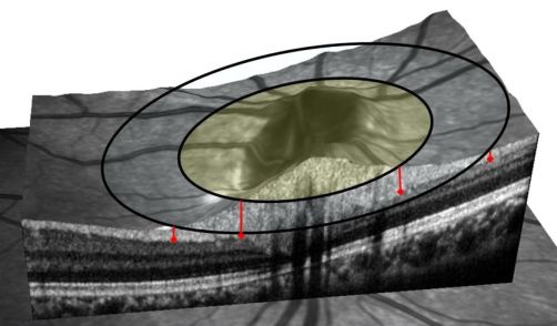
example look at the image below. If the OCT uses a large ring to
assess the RNFL (outer ring in the figure), then the measurement will
be much thinner than that from a smaller diameter scan (shaded inner
ring). The RNFL thickness is shown by the red lines, indicating if the
scan is too large relative to the disc size then the RNFL will appear
to be abnormally thin, when really the scan is farther from the optic
disc center. The
software allowed us to assess the RNFL at set distances from the
optic disc center from lines scans or misaligned circular scans.
The software specifically works only with the Heidelberg Spectralis device and HEYEX software. This software is NOT intended for clinical assessment but rather as a tool to help assess RNFL thickness. You can download the free software package in a zip file here. By downloading you agree to the terms listed below. A tutorial and description is given below.
File size: 0.6 MB; Updated 6/6/2018
Install
on any Windows PC, you do not have to install it on your
Does not require any external plugins. It does not need the registry. Simply create a folder to install and delete the folder to uninstall the software .
Limitations:
-Tested
on
Heidelberg Eye Explorer (HEYEX) version 1.9.13.
(Spectralis viewing module version
6.6.2.0) and older versions
-Currently the program only processes circular or horizontal line
scans.
-Use at your own risk (see terms below).
Requirements:
-Windows
XP,
Tutorial
|
|
|
|
|
|
A
copy of this tutorial is also provided as a pdf
file.
The entire program is stored in a compressed zip file. To install,
simply open the zip file, and drag the contents to a folder where you
will store the HEYEX export files (or to some folder on another
workstation if you want). In this example we will be using the C:\ExportFiles
folder.
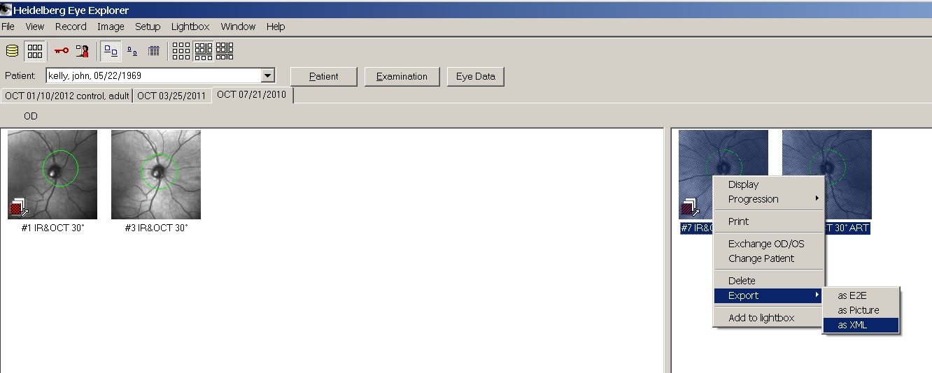
Now
open an OCT data set in HEYEX. For instance we will open a set of
scans from my left eye. Drag the mouse to select the scans then
right-mouse click to export the scans in XML format:
If
you
don't see the XML option, then turn on the option in HEYEX
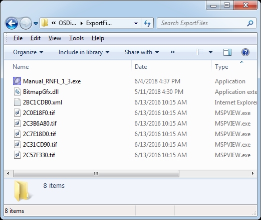
The exported files should be placed in the same folder as the app
(Manual_RNFL_1_3.exe file). For this example I use the C:\ExportFiles
folder, but any folder or flash drive is OK too). You should see a set
of .tif and .xml files in the folder. You can repeat
this again for more patients since the program can batch run through
all exported files.
Now double-click the Manual_RNFL_1_3.exe to start.
You
will see this message if you did not export properly or copy the
files. Make sure all exported files are in the same folder as the app.

The
program should automatically detect the exported files and immediately
start with the first exported scan. Left-click the mouse in the center
of the optic disc. Now you will see a yellow square mark this
location. While you hold down the mouse button, a yellow circle will
be shown to demonstrate the desired circular scan. Right-click the
mouse to set the location of the fovea. Now you will see a blue square
and "F" mark this location.
Notice we can set the size of the desired circular scan by entering
the value in the box in the lower left (labeled circular scan
radius µm). The initial value will be the radius of the actual
acquired scan (that depends on your refraction). I have a smaller
optic disc of 1330 microns. For this example, I scaled the desired
scan to 1680 microns, then repeat my left-mouse click on the center of
the optic disc to see the smaller ring
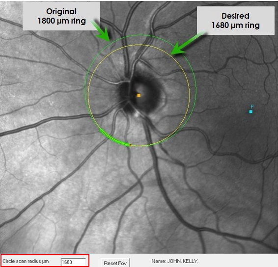
Now
you
see the yellow (desired scan) intersects with the actual scan.
Matching areas are shown by the filled circles along the green circle
scan. >
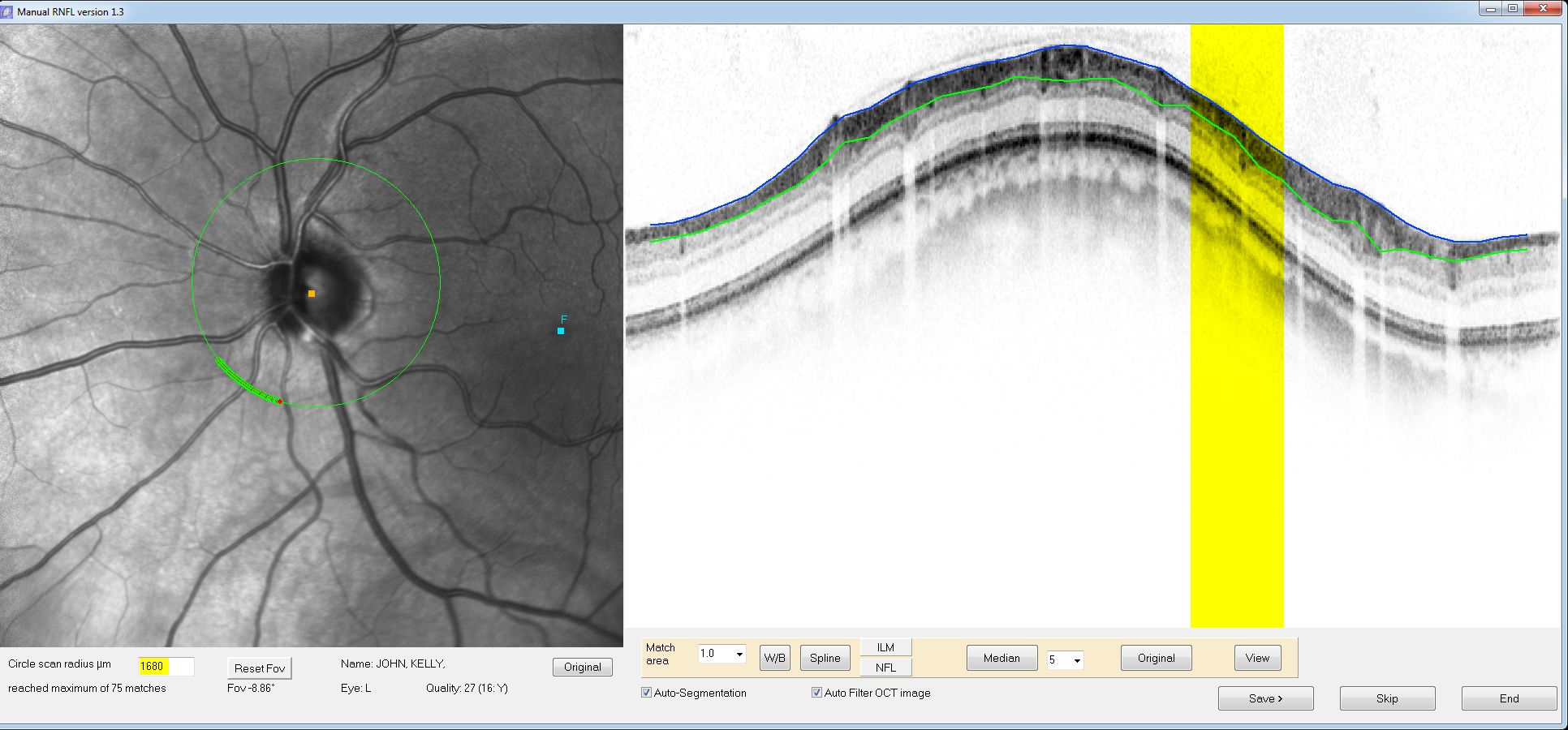
The
corresponding
match locations on the OCT scan are now highlighted in yellow. Because
there are many matching locations, three buttons on the lower toolbar
will become active (“Spline”, “ILM”, and “NFL”).
These allow for a spline fit of the Internal limiting membrane and the
nerve fiber/ganglion cell layer interface. The program will attempt
automatic segmentation of the ILM/NFL boundaries (blue and green lines
respectively). Click the NFL button (or click the green line) to edit
the segmentation. You can click and drag the red position markers to
custom fit the RNFL borders. Similarly you can edit the border of the
internal limiting membrane by clicking the ILM button (or clicking the
blue line).
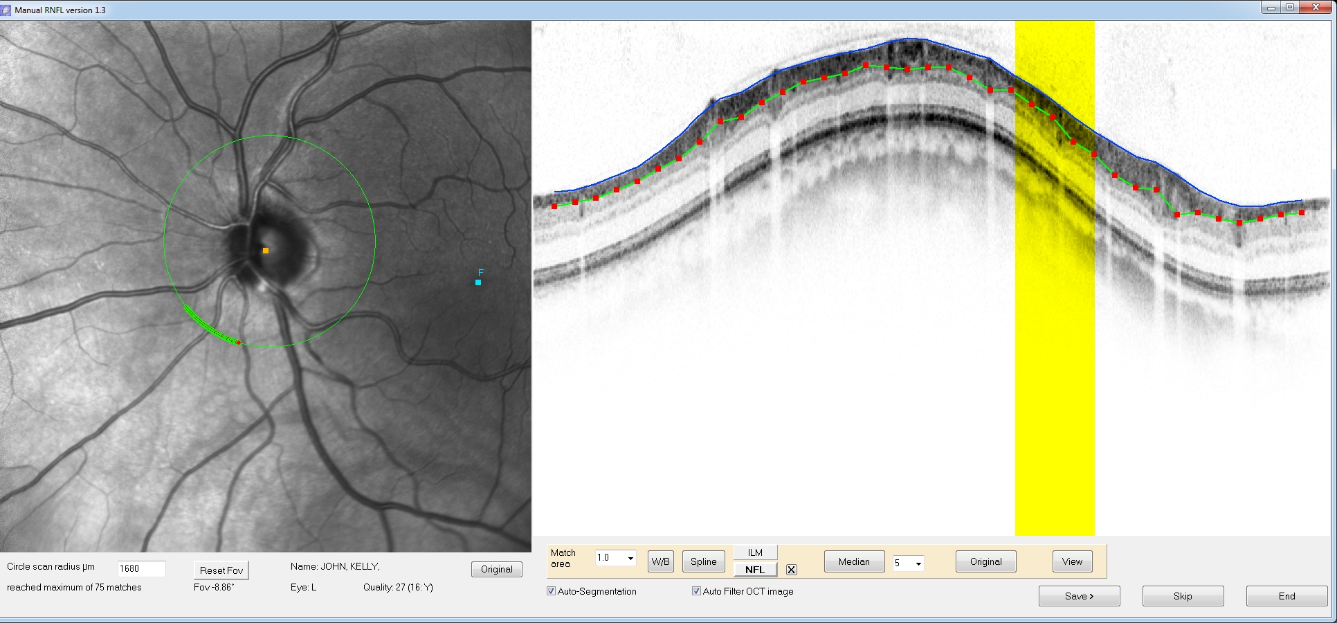
You
can
click and drag the red position markers to better align your manual
segmentation (this process is similar to the manual adjustment in
HEYEX software). If you double click on a position marker another
position marker will be added next to it. Hold down the delete key and
hover the mouse over a position marker to delete it.
What if the automatic segmentation does a poor job? The automatic segmentation is not optimized and therefore is prone to errors. You have several options:
1) Delete the segmentation by clicking the "X" next to either the ILM or NFL button. Then you can manually draw a line along the ILM or NFL borders on the OCT image. The speed at which you draw the line sets a relative resolution. If you make a mistake don’t worry, when you are done the program will automatically place position markers when you are done drawing.
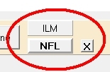
2) Right-click and drag on the
OCT image to change contrast and brightness (e.g., 'windowing'). After
you finish a new segmentation will appear. You can click the "Original"
button to revert back to the original image.
Now
click the View button in the lower right tool panel. You will see the
results of your manual segmentation plotted on the normative template
(current norms as of Heidelberg Eye Explorer HEYEX viewing module
version 5.4.6.0).
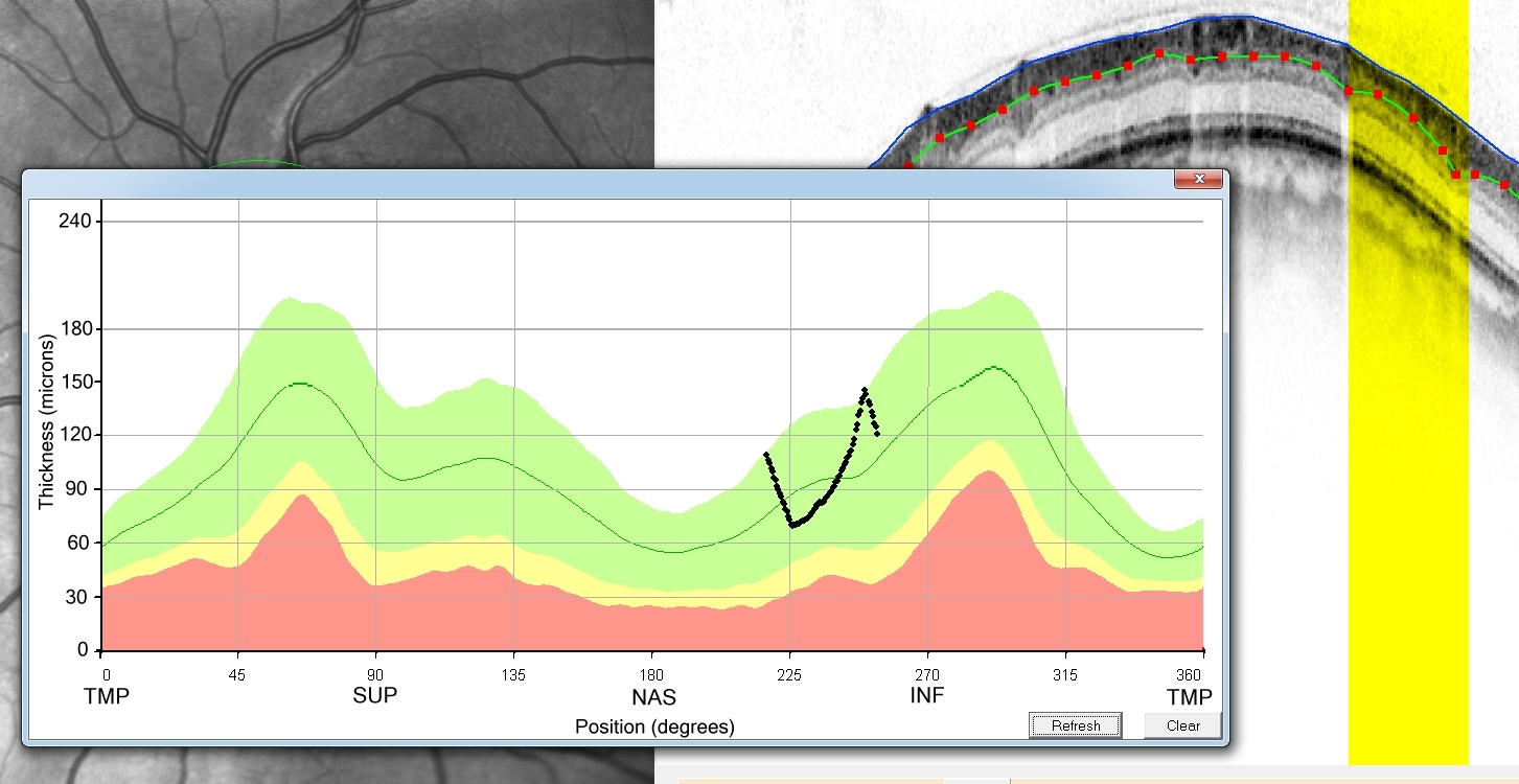
As
you can see, the RNFL thickness falls in the normal range (glad to see
that for my eye!). The data points at the matching location have been
adjusted for the position (degrees) by using the currently chosen
fovea location. Note that if you right click on the SLO image, the
fovea will be relocated and the angle on the template will be
automatically updated (Note that HEYEX may use an approximately 8 deg
correction). If you change the position markers then click the
"refresh" button to update the changes on the graph. If you want to
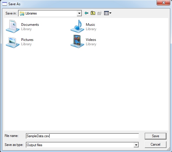
keep the measurements then click the Save button. You will be
prompted for a name of a text file to store these measurements. You
can save it with a .csv extension for automatic opening in Excel
or your favorite data analysis package.
If
you don’t want to save, then click the “Skip” button. Either
way (Save or Skip), the program will automatically load up the next
exported image for you. You can repeat this process until all exported
files are done. Similarly all measurements will be appended to the
normative template via the View button and appended to the text file,
if saved.
Ok,
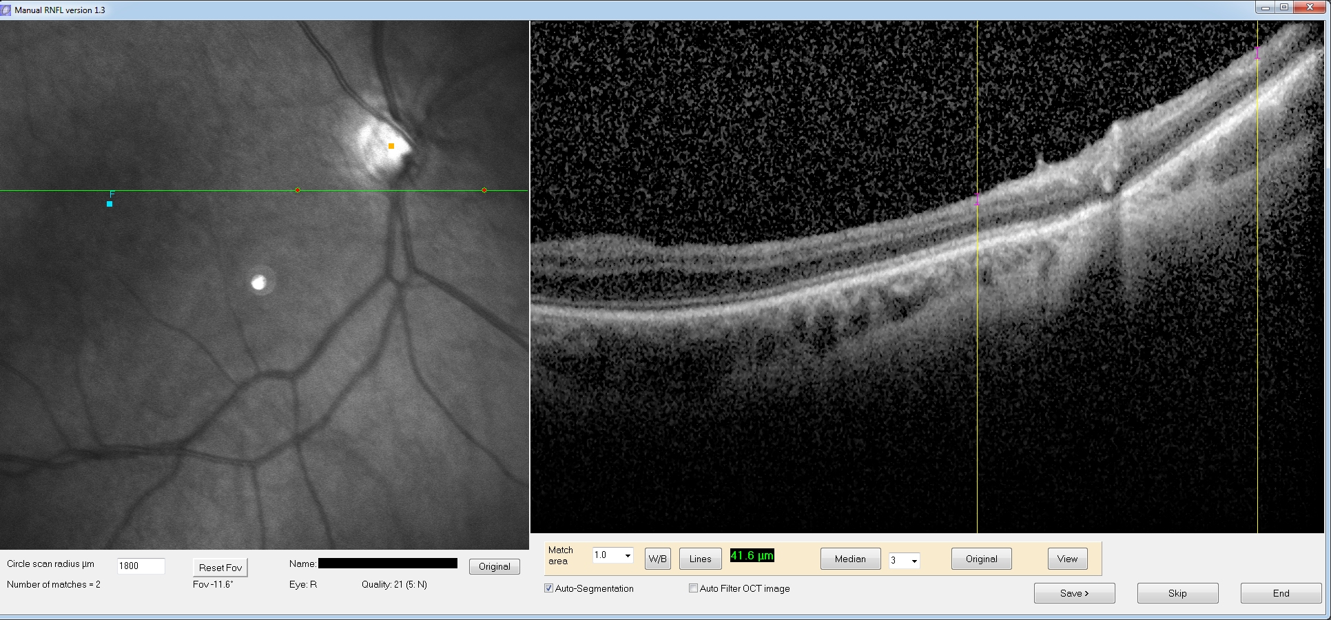
but what about line scans? Here we do the same process, but
since it is a line scan we will have only 1 or 2 matching locations.
Now there is no “Spline” button since we don’t need it. We have to
measure RNFL thickness at 1 or 2 discrete locations. Simply click and
drag on each yellow line (the match locations) and a purple line will
be drawn. Also you will be updated on the length in the lower tool
panel. For example, for a patient image, I have drawn a line on the
each match point (RNFL thickness was 41.6 microns on the left line).
Eventually
you will finish all the exported images. After the last image you will
see the message:
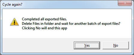
If
you click No then the program will end. If you haven't already saved
your data, a dialog box will appear to make sure your measurements
will be saved. If you click Yes, you will be prompted again to make
sure you want to delete all exported files (just the ones in this
folder). If you confirm then the files will be deleted and the program
will prompt you it is waiting for a new set of HEYEX exported files
(see step 1 above).
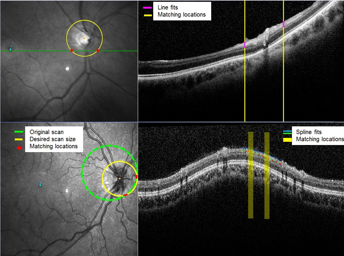
Here
are sample screens of optic nerve hypoplasia:
![]()
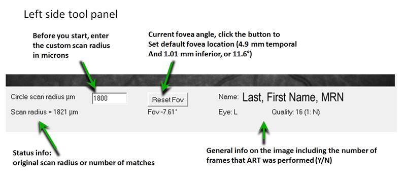
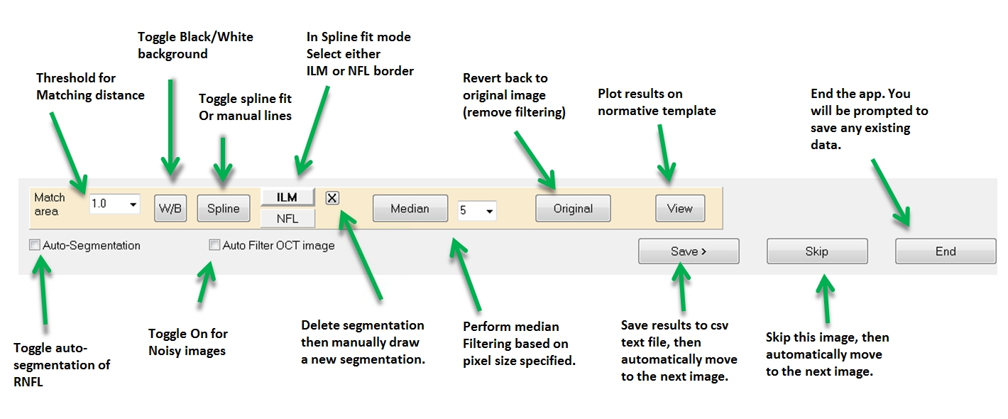
Here
is a review of the tool panel. It should be easy to understand if
you work with HEYEX.
|
|
|
|
|
|
Format
of the output file
When
you click the save button, the program will store the values in an
ASCII text file with comma delimited values. That means it can be read
by many analysis programs that accept CSV files (like EXCEL, SPSS,
etc.)
The
fields in order are self descriptive as such:
LastName,
FirstName,
MRN,
Eye,
OriginalRadius_um,
NewScanRadius_um,
RNFL_Angle°,
RNFL_Thickness_um,
Disk_X,
Disk_Y,
Xpix_on_SLO,
Ypix_on_SLO,
Fovea_X,
Fovea_Y,
Fovea_ang°,
Focus,
Quality,
Met_PositionTolerance?
License
________________________________________
The
License for the software follows a restricted freeware / MIT license
with additional disclaimers. Copyright (c) 2016, John P. Kelly
Updates and software modifications might occur in the future,
particularly for better automatic segmentation of layers.
Permission
is hereby granted, free of charge, to any person obtaining a copy of
this software and associated documentation files (the "Software"). You
are not granted permission to deal, copy, modify, merge, publish,
distribute, sublicense, and/or sell copies of the Software. The above
copyright notice and this permission notice shall be included in all
copies or substantial portions of the Software. You are not allowed to
redistribute the software. You cannot use the software for payment,
nor for use as any material for which the user is asked to pay. You
are not entitled to hide or deny my copyright.
THE
SOFTWARE IS PROVIDED "AS IS." THERE ARE NO WARRANTIES WITH REGARD TO
THIS SOFTWARE, INCLUDING ALL IMPLIED WARRANTIES OF MERCHANTABILITY AND
FITNESS, IN NO EVENT SHALL JOHN KELLY OR SEATTLE CHILDREN'S HOSPITAL
BE LIABLE FOR ANY SPECIAL, INDIRECT OR CONSEQUENTIAL DAMAGES OR ANY
DAMAGES WHATSOEVER RESULTING FROM LOSS OF USE, DATA OR PROFITS,
WHETHER IN AN ACTION OF CONTRACT, NEGLIGENCE OR OTHER TORTIOUS ACTION,
ARISING OUT OF OR IN CONNECTION WITH THE USE OR PERFORMANCE OF THIS
SOFTWARE.
