Variable-Pole-Pitch Linear Synchronous Motors
And their Potential in Automatic Transportation Systems
by
Among many other things, Markus Szillat wrote on January 5, 2000, "With LSM there will be the challenge of somehow dividing these [acceleration] ramps into many different sections, while controlling them all centrally, so that vehicles in different sections can 'see' different frequencies. Unless they can somehow organize vehicles into platoons that will all get on and off the guideway together—a big logistics problem— vehicles at different parts of the ramp will have to have different speeds, hence be in different control circuits. I'm guessing these control circuits won't exactly be terribly simple, either—and neither will the control algorithms."
At the time you wrote that, Markus, I had few answers for the "challenge" you spoke of, but the creative juices continued to churn—on their own schedule. The following new variable-frequency concept meets the requirement that vehicles in different parts of the ramp will have different speeds. But interestingly they will all receive the same frequency at any point in time, and all of the linear synchronous motors (LSM) will be running synchronously on that same power—at different speeds. Only one control circuit will be required, and the cars will use it in turn for the final merge only, not for their acceleration per se. And to this neophyte, the control algorithm needed appears to be very simple.
I propose to accomplish these contradictory-sounding things by changing the pole spacing or pitch of the LSMs in the ramps in conjunction with power having standardized repeating saw-tooth steps of increasing frequency. The following explanations will be at an elementary level since my own understanding of electrical engineering and LSMs is elementary, and some readers may share my limitations in these things.
Inversion of Linear Synchronous Motors
LSM can be designed with the field magnets in the guideways and the armature coils in the cars or pallets, or vice versa. For the following reasons I propose putting the magnets in the guideways and the coils in the cars: (1) The price of copper would skyrocket if we were to use a lot of it in tens of thousands of miles of guideway. (2) Wound coils on laminated pole structures appear likely to require more expensive manufacturing steps than those required in composing and processing the permanent magnets. (3) The cost of advanced permanent magnets (such as Nd-Fe-B) is bound to come down if we purchase them in huge quantities. Fortunately most of the "rare-earth" elements, including samarium and neodymium which are used in advanced magnets, are not really rare in the earth's crust. (4) With intermittent traffic it would take less energy to power the cars than to power miles of little-occupied guideway. (5) Putting the coils in the cars seems to offer important control advantages. (6) Lastly, the variable-pole-pitch concept I now propose might be impossible if the coils were in the guideways and the magnets in the cars.
An obvious disadvantage of putting the armature coils in the cars is that parallel trolley wires will be required at the guideways, and sliding or rolling "brush" contacts required in the cars. But this old technology is very well developed and successful. It is used in thousands of streetcars, trackless trolleys, and electric trains worldwide. For simplicity single-phase power will be assumed the following explanations, but if we choose three-phase power (as we probably will) the same principles will apply.
Pure synchronous motors have no torque ("thrust" in this case) when they are not running in synchronism with their applied power. Therefore several of us have been proposing to vary the frequency of the power on the ramps in order to accelerate and decelerate the cars. The vehicles on the ramps would at all times be running synchronously with their frequency-controlled power, but they would be asynchronous with respect to each other and with respect to the constant-frequency guideway power and traffic.
Variable Pole Pitch
Another way to vary the speed of the cars while their motors are running synchronously with their power is to change the pitch of the magnetic poles in the motors. If the frequency of the power applied to two linear synchronous motors is the same, but one motor has pole faces one unit long (in the direction of the guideway), and the other has pole faces eight units long, the latter motor will have to travel eight times as fast since it must take steps eight times longer than the first motor does.
At first I believed that this concept of changing the speed of a synchronous motor by varying the pole pitch was original. But I now find that US Patent # 3,470,827 titled "High-Speed Land Transportation System, issued to R. F. McLean, Oct. 7, 1969, and assigned to General Motors, contains the following statement. "When the stator is embedded in the trackway, variable speed during acceleration and deceleration can be obtained from a constant frequency power source by increasing the pole pitch as the distance from the station is increased." McLean provided no details. The subject of that expired patent was air-bearing levitation, not LSM.
In the acceleration ramps we can install different lengths of field magnets on different sections of the ramps. I propose that this variable pole-pitch LSM concept be used on the ramps in conjunction with variable-frequency power such that the motors would always run in synchronism with the combination of local-motor-pitch and local-frequency. The diagrammatic illustration of Figure 1 is intended to help explain this idea. It is not to scale. At the low-speed (left) end of the acceleration ramp the field magnet pole faces are short and spaced closely together (fine pitch). The poles then lengthen or increase in pitch toward the right in several discrete steps.
Variable Armature Pole Pitch to Match the Field
We must correspondingly vary the effective armature pole-pitch in the cars as they pass over the magnets such that the armature is always operating at the same pitch as the local field. These corresponding armature pole-pitch changes will not be made by changing the physical geometry of the laminated iron cores or slots, however. As shown in Figure 2 (drawn at a larger scale than Figure 1), the armature coils are all made the same size. The minimum or basic armature pole pitch will be the same as the minimum magnet pole pitch in the ramps. However, the armature coils can be electronically commutated in multiples such that each successive step (corresponding to successive ramp-magnet sections) produces an effective pole pitch twice the pole pitch of the previous step.
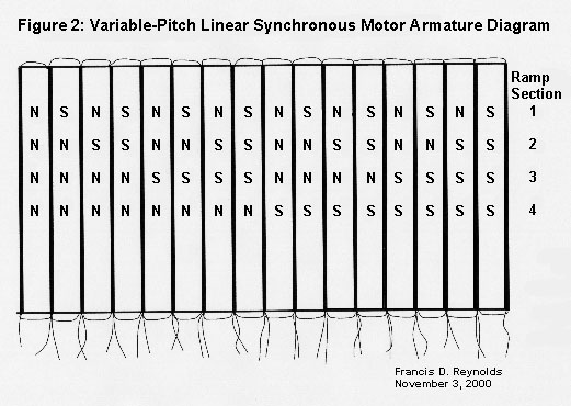
In different words, the AC power will produce a traveling magnetic wave in the armature poles. The length of that wave (effective pole pitch) will be raised in steps during acceleration of the cars, and kept in synch with the step changes in pitch of the guideway field magnets as they are passed. The armature pole pitch is the distance between adjacent armature slots at first, producing a simple N S N S N S N S pattern. Then the pitch will effectively become the distance between two slots, producing a NN SS NN SS pattern; then to four slots, giving NNNN SSSS NNNN SSSS; and finally a single pole will be the distance between eight armature slots, NNNNNNNN SSSSSSSS. Each of these armature changes will be made at the instant and place where the corresponding field-magnet-pitch-change occurs. Four-step acceleration is not sacred, but it looks like a good initial choice.
With the hardware geometry shown in these figures, if we smoothly raise the frequency of the applied power to a car starting at the low-speed (left) end of an acceleration ramp the car will smoothly accelerate until it reaches the step where the magnet pitch suddenly doubles. At that point the frequency of the power will be instantly halved. At the same instant the armature-pole pitch will be commutated to match the new magnet pitch. The frequency will then rise smoothly again until the car reaches the next jump in magnet pitch. This process is repeated a number of times until the car reaches guideway speed. At the steps, in order to retain synchronism, the product of the new frequency and new pole pitch must equal the product of the just previous frequency and previous pole pitch.
Matching Frequency Steps
The armature-power frequency changes are illustrated graphically in the upper part of Figure 1. In the central part of the ramp the frequency smoothly rises to double, drops back at a step in magnet pole pitch, and rises to double again as it reaches each next step. Note that the X-axis of this frequency graph represents time. All of the frequency steps are identical except the first one, which starts at zero frequency in order to provide initial starting torque. The acceleration is constant and equal in all sections until guideway frequency and velocity are reached.
At constant acceleration, distance is proportional to the acceleration-time squared. The cars must stay on each section of the ramp for the same length of time in order to use the same frequency steps. So as the speed increases the sections of constant magnet pitch on the acceleration ramp will be made progressively longer.
This whole process closely parallels gear shifting in our automobiles. The different magnet-pitch sections of the ramp correspond to different gear ratios. And the several smoothly increasing then suddenly dropping power-frequency steps correspond to the several increases and drops in the speed of the engine during the acceleration and gear shifting of an automobile.
The advantages of this stepped-pole-pitch concept include elimination of any efficiency reductions or design problems that may be inherent in trying to use an excessively broad range of power frequencies. It would also have the advantage of allowing several cars to accelerate simultaneously on the same ramp. Each of four cars could be receiving the same increasing-frequency power, but each would be operating in a different "gear" section of the ramp and running at a different speed. The number of ramps needed at a particular location would be determined by the amount of entering traffic and by the time required to process entering cars, not by any limitations of the ramps per se.
Adding stepped-magnets in the ramps and stepped coil-pitch capability in the cars as proposed would have no effect on the cost, safety or complexity of the guideways proper. But these features would increase the complexity and cost of both the ramps and of the cars. The efficiency of the cars on the guideways would be slightly reduced due to the removal of some of the core iron in the armatures to make the additional slots required for the variable-pitch acceleration system.
Merging
A car will be held stopped until the computer identifies an upcoming gap in the guideway traffic into which it chooses to merge that car. The merge-gap selections will be made by means of the precise dead reckoning data that guideway's computer will maintain for all cars on that guideway. It will count the alternating-current cycles fed to each car and know exactly where each car is at any point in time. This will be true both on the constant-frequency guideways and in the variable-frequency ramps during acceleration.
The acceleration part of all ramps will have the same precise pole-pitch steps and be fed the same precise frequency steps. Therefore the computer can time the start of the acceleration of any car entering the system or transferring to another guideway so that it will arrive at the merge point at exactly the same time as the arrival of the chosen gap in the traffic. The computers can always provide the same lead-time, since all of the factors affecting the required lead-time can be held constant throughout the system. The action will be like spur-gear teeth mating, where a tooth in one gear is prescheduled to arrive at the merging point at exactly the time a gap between teeth in the other gear will arrive there. No extra space is needed nor desired, since the merge is always timed perfectly.
Safety Features
Thus merges could occur automatically without further control beyond the programmed lead-time. But to provide a safety-net backup system a short "merge position" section will be added to each acceleration ramp as shown at the right in Figure 1. While in this section the entering cars will run at approximately synchronous speed. Sensors will compare a car's actual position to that of the gap it is now running parallel with, and make any final small changes in its power frequency that may be required to match the car's position perfectly with the gap in the guideway traffic. Human drivers do the same thing in highway merging, but very much less accurately and therefore requiring very much more clearance between cars. This job will be easy for computers. We would be guilty of outdated thinking if we let human limitations restrict the design of our automatic system.
In the unlikely event that some failure, any time after acceleration has been initiated, makes a safe merge impossible, the system will abort the merge, decelerate the car, and route it back to the streets via the straight-ahead abort section as shown in Figure 1 above. This is a safety feature that highways lack. When we merge with a highway, if something goes wrong at the last second there may be a collision on the highway, rear-enders on the ramp, or both.
Ramps to interconnect different guideways would be similar to the system-entry ramps described. However, they would need to be double-length, containing both deceleration and acceleration sections, since a car exiting one guideway would sometimes have to be stopped to wait for a gap in heavy traffic on the receiving guideway.
An open-loop system would be desirable from a simplicity and low-cost standpoint, but I am advised that it is unlikely that such a system could be adequately safe. Therefore we will probably use some kind of feedback. It is also my understanding that a closed-loop system may alleviate the hunting and dropping-out of sync problems that we have been warned of.
In my opinion LSM synchronized guideways with asynchronous ramps (with or without the variable-pole-pitch feature) will be safer, more reliable, and the algorithms will be simpler than those for asynchronous guideways would be. With the "emergency turnaround loops" I propose (to isolate a troubled section of guideway), local problems such as power outages will have no effect upon the rest of the system. [see /hilo2.htm, Figure 1, at this website].
If a specific car on the guideway develops a problem it will still be carried forward by its own kinetic energy, to a greater or lesser extent depending upon the nature of the problem. The heavier the traffic the safer it will be, because with close spacing the car behind will start pushing a disabled car while their relative velocity and relative kinetic energy is small. If there should be a chain-reaction accident it will be limited, by the isolation system, to the section of guideway where it originates. The shorter the isolateable sections the more limited the possible damage, but the more expensive the system.
If the power fails or is turned off in a guideway section that section will instantly become an isolated loop, but the cars will still be electrically connected with each other through their power trolleys and will instantly autosynchronize through regenerative braking. The cars would maintain their spacing and gradually coast to a stop. Then their drivers will drive them from the disabled guideway under street power.
Brakes and Stopping distance
I do not want energy-dissipation brakes on the cars that could be used when they are on the guideways at synchronous speed. The only braking needed is the inherent synchronous regenerative braking that will be provided by LSM on steep downgrades and in the deceleration ramps. In fact I argue that the mere presence of any other guideway brakes on the cars would decrease the safety of the system. If other than synchronous braking were to be applied to a car by accident, that car would go asynchronous and become a slower object subject to being rammed. The fastest way to cause a pileup on a busy highway is to slam on the brakes of a car. The safety objective in a closely spaced synchronous system will be to try to maintain vehicle spacing at all times. Autosynchronization will maintain spacing more perfectly (and far more simply) than any computer-generated braking commands to individual cars could.
The phrase, "safe stopping distance," is misleading. We cannot mean to provide enough distance to stop before we hit the car ahead if it would stop instantly. This would be a totally unreasonable requirement because the momentum of the cars ahead wouldn't let them stop instantly even if all of their wheels fell off. Existing highway use doesn't come close to meeting a brick-wall stopping-distance requirement. If we did we would need many more lanes. And providing such a stopping distance in an automatic system would be even more unreasonable. A (I think the) primary objective of an automatic dualmode transportation system will be high capacity. Its capacity would be degraded if any stopping-distance clearances were provided. And no stopping distance is required in an automatic system.
Cautious drivers on the highways attempt to adjust their speed to the speed of the other cars close to them, through brakes and throttle—they approximately synchronize with the traffic. And that is what an LSM guideway will do automatically and precisely. But since the response time of an automatic system will be hundreds of times shorter than the reaction and action times of a human driver pushing floor pedals, the clearance between cars in an automatic synchronous system can be close to zero.
In fact, except for a few inches of clearance that will probably be required for merging, it would be best if there was no clearance at all between the cars on the guideways. Advantages of short headway include the drag reduction we will gain from platooning, the high system capacity that short headways provide, and things in contact with each other can't collide with each other.
We don't worry about the cars in a railway train following each other very closely. As Markus wrote on 12/1/00, to the Transit-Alternatives Discussion Group, "The cars are separated from the locomotive by zero [headway], yet this is not a safety concern." We feel that way because we have learned to trust close-coupled trains. Conversely, we have learned to distrust close headways on our highways. We must reexamine old convictions when we are designing something new. When conditions are different our established emotional responses can mislead us. On LSM guideways the cars will be coupled by magnetism instead of by railway couplers; but they will be coupled—like "safe" trains are.
Still another advantage of true synchronism between the cars on the guideways is that it eliminates the need for a lot of expensive and failure-prone proximity sensors and velocity-control systems. With synchronous cars the perfect dead-reckoning position data we will have for every car on every guideway at every instant will provide the information required for merges as well as for the navigation of each car. The ID chip in each car will be reread at each demerge and new merge in the trip, to confirm that the vehicle is indeed where the dead-reckoning data shows it to be.
I believe this system will have far fewer and less-catastrophic accidents than our highways and railroads do, but absolute safety will elude us. There has never been and never will be a perfectly safe transportation system. How much safety are we willing to pay for? For example: We know that accidents repeatedly occur at railroad crossings; and we know that this problem could be completely eliminated very rapidly if the decision-makers wanted to spend the money for an overpass or underpass at every railroad crossing. Decisions have apparently been made that eliminating the annual loss of life at railroad crossings wouldn't be worth the expense. But such decisions are not usually announced publicly in those terms.
Practicability
I recognize that this article and much of what I and other LSM advocates have previously written hinges on the viability of LSM for guideway use. Dr. Richard Thornton, founder, and Dr. Tracy Clark, Director of Engineering of MagneMotion, are skeptical of that viability. But technical history and personal experiences as an inventor engineer tell me that these problems will probably be solved, in one way or another, when additional good creative engineers are put to work on them.
We have had intelligent, educated, experienced people throughout history who told us that mechanical power from fire was impossible, as was flying, breaking the sound barrier, the atomic bomb and atomic energy, space travel, heart transplants, etc. Surely the development of stable non-slip LSMs will be a simple job by comparison.
Several dualmode-system inventors are proposing rotary synchronous motors instead of LSM. This would definitely be cheaper than LSM guideways, and would supposedly solve the problems that Thornton warns us of. But minor variations in vehicle wheel diameter and minor wheel slip would prevent rotary motors from providing the highly advantageous truly-synchronous guideways. Cars using rotary motors could be synchronized by the addition of powered cogwheels on the cars and a mating rack on the guideways, but these would wear and be noisy. As a mechanical engineer they don't appeal to me at all. The kind of rack I prefer on the guideway is the stator of an LSM.
Ed Anderson, Andreasson, Tim Hayward, Markus Szillat, and some others debate the definitions of "point-synchronous control," "deterministic systems," and other terms that are not part of my working vocabulary. I need some help. Whatever you choose to call it, please have another look at the operating characteristics of a system (HiLoMag) that would use LSM to provide constant-speed synchronized operation of all cars on all of the interconnecting guideways twenty-four hours a day. And envision asynchronous ramps connecting all of these guideways to each other and to our streets and highways.
Since the guideways would be synchronous and all of the ramps would be asynchronous with respect to the rest of the system, each section of guideway would act as an independent system with respect to time. The position of any car on a guideway will be known by simple constant-speed dead reckoning. But on the entry ramps and the ramps between guideways the dead-reckoning clock for each car will be reset at each new merge, since the exact time of the merges cannot be predetermined. (There will be no clear paths; entering cars will be assigned the first available gap in the traffic on each guideway they need to use.)
I don't know if this system fits one of your existing terms or not. Maybe you will need to assign it a new descriptive category. Keep me posted.
Last modified: December 05, 2000