Tank Drainage Derivation
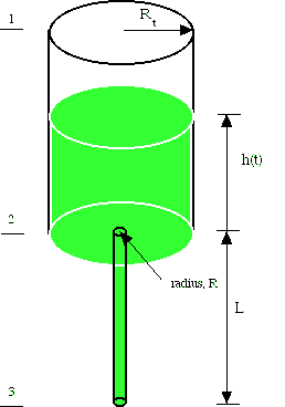
Consider the tank problem illustrated in the figure. The tank drains, but as the height gets smaller, it drains more slowly. This problem can be solved by using a macroscopic mechanical energy balance and mass balance, following Bird, et al.(ref). The mass balance is

![]()
The term m
tot is the total mass of the system, and![]()
is the mass flow rate in or out of the system and <v> is the average velocity, averaged over a cross section of the inlet or outlet. The mechanical energy balance is
![]()
where the terms represent the time variation of the kinetic energy of the system, the time variation of the potential energy of the system, and the difference between the inlet to the outlet of the kinetic energy, potential energy, and pressure energy. K
tot is the total kinetic energy of the system, and Ftot is the total potential energy of the system. The terms on the right hand side are differences from the inlet to the outlet; the Æ terminology is positive going out and negative going in. The balance is made over a control volume which includes the air above the fluid down to the hole. The terms are: <v3> is the velocity to the third power, averaged over the area of the inlet or outlet,![]()
The terms are evaluated for the case of a constant velocity profile, i.e. the velocity does not vary in the direction transverse to itself. The mass balance becomes
![]()
The kinetic energy term is
![]()
where R is the radius of the small hole at the bottom, R
t is the radius of the cylinder above, h is the height of the fluid in the cylinder, and v2 is the velocity out the hole. The kinetic energy of the system that changes in time is due to the velocity of the upper surface of fluid; while the velocity varies with time in the small hole, it does so in an infinitesimal volume and doesn’t contribute to the integral. However, continuity is used to express the kinetic energy involving the velocity at surface 1 in terms of the velocity at surface 2.![]()
The potential enegy of the system is
![]()
When the velocities are considered constant across the tubes, the kinetic energy term is
![]()
(Recall that the top surface is in air, and the density and velocity are very much smaller than those in the fluid at the outlet). Combining all terms gives
![]()
Divide Eq. (4) by
r p R2 / 2 to get![]()
Likewise, the mass balance is
![]()
Bird, et al.(ref) manipulate this equation by rearranging Eq. (1) to solve for velocity
![]()
and substituting into Eq. (5). The final result is
![]()
This is a second order equation, which is an initial value problem. The initial conditions are that
![]()
The so-called Torricelli’s velocity is
![]()
Eq. (6) can be integrated analytically, but the result is cumbersome (ref). It can also be integrated numerically as an initial value problem. One defines
![]()
and then integrates the two initial value equations

The initial conditions are.
![]()
Solution method (link)
As a variation of this problem, consider the case when there is a straight length of pipe at the exit.

Now there is viscous dissipation in the pipe. The mechanical energy balance now has additional terms on the right-hand side.
![]()
The viscous dissipation for the contraction is usually expressed as
![]()
where e
v is a constant depending on the contraction ratio.![]()
The viscous dissipation in the straight pipe is
![]()
where f is the friction factor. Now the mechanical energy balance is
![]()
where f(v
2), although it may be assumed constant over some time period. After dividing by r p R2 / 2 we get![]()
Continue on to solve the problem.