
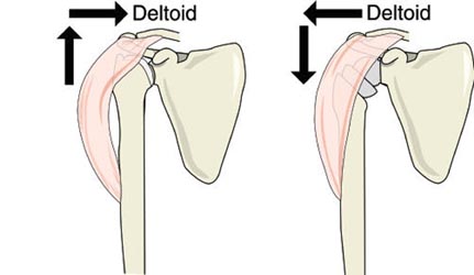
Welcome to The UW Shoulder Site @ uwshoulder.com
Please note that information on this site was NOT authored by Dr. Frederic A Matsen III and has not been proofread or intended for general public use. Information was intended for internal use only and is a compilation for random notes and resources.
If you are looking for medical information about the treatment of shoulders, please visit shoulderarthritis.blogspot.com for an index of the many blog entries by Dr. Frederick A Matsen III.
Encore Reverse Technique Guide
Equipment Needed
Revisions Add:
Setup
Place templated x-rays, clinic notes and progress note on x-ray box.
Prefill-out orders and setup pt in a beach chair position. The operative arm should be able to hang off bed as shown below.
.png)
.png)
You should circumferentially wrap cloth tape around the patient's chest and table to prevent pulling the patient off of the table during the surgery. This taping is in addition to use of the patient's normal safety belt.
You should NOT be using the old RA table of Beachchair attachment for this case. If for some reason you are using these systems (such as to help with fluoro) DO NOT REMOVE THE SHOULDER SUPPORT! Removing the shoulder support under the operative side may seem like a good idea but the patient will eventually migrate off of the table.
The anesthesia team and ortho team should work together to tape the patient's head down. You may need to use a clipboard to support the head (if using the RA table or Beachchair attachment). We do not secure the head in a brace as shown above.
A 1010 drape should be secured around the patients neck and the free end secured to the tape holding the patients head. Securing the free end prevents it from falling onto the sterile field when prepping.
ROM of the operative shoulder should be measured and recorded on the board in the following order: FE, ER, IRA, ERA, CBA.
Double Prep
A member from the ortho team needs to wash and gown and prep the patient's operative side. ChloraPrep is the prep of choice.
Prep from the middle of the chest out to the wrist, followed by armpit, followed by wrist, hand and fingers. This should be done a total of three times.
The first drape is setup under the patients head, operative arm and over the patient's waist. If possible, the drape should be tucked under the patient's belt. This draping is done by the nursing staff or other member of ortho team.
The first set of gloves are removed and the second prep is performed in the same manner as the first.
The second drape is setup over the first in the same manner.
Draping
After the two initial drapes are placed under the head shoulder and over the waist, one drape is place over the chest and feet. This should go from the patient's armpit to the patient's neck.
Another drape is placed over the head and overlaps across the chest drape.
The three corners where these drapes come together are stapled. There is no need to staple the drapes directly to the patient.
The arm should be covered with a stockinet and a dry sponge placed in the patient's axilla.
|
A clear adhesive plastic is used to cover all exposed skin.
At some point a timeout will be performed by the circulating nurse, attending and anesthesia team. The room should otherwise be free from any talking or other distracting noises during the timeout. |
|
Approach Prior to making an incision, a formal timeout will be performed by the attending circulating nurse, and anesthesia team. The room should otherwise be free from any talking or other distracting noises during the timeout.
Make your incision from the coracoid down, 10 cm or so. |
|
A scalpel should be used until the surgeon reaches muscle. Mayo scissors are then used to dissect through fascia to locate the cephalic vein and deltopectoral interval. |
The deltopectoral interval should be blunt dissected with the surgeon's index finger, taking the vein laterally. Make an effort to preserve as much deltoid muscle as possible.
The motion interface under the deltoid and pectoralis should be freed up and the conjoined tendon located.
Remember to free up the conjoined tendon on its lateral side so that the tendon can be retracted medially. Incising into anything medial to the lateral border of the conjoined tendon can result in musculocutaneous nerve injury.
When the lateral border of the conjoined is freed up, use a medium Richardson retractor to pull the conjoined medially. Use a Balfour to expose the rotator cuff /superior humerus.
Bursa should be removed to better visualize the subscapularis. Identify the long head bicep tendon and plan to free the subscapularis as close to and medial to the biceps without cutting it. If surgery is for rotator cuff arthropathy, it is likely that the long head biceps will not be in its anatomical position.
Free the subscapularis from the humerus and tag stitch it twice. Once it has been sufficiently freed, the humeral head should easily dislocate.
|
Humeral Cut
This resection should be made at 30 degrees of humeral retroversion. |
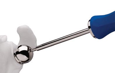
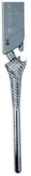
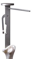
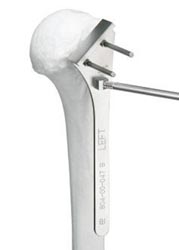 The
Encore system has a humeral cutting guide to help mark your cut.
We do not pin it in place as shown in the technique guide (image right).
Instead, hold it in place at 30 degrees of retroversion and use a bovi
to mark your cut. The surgeon may opt to cut a parallel line below
this to allow for more glenoid exposure and to seat the humeral
component lower. The
Encore system has a humeral cutting guide to help mark your cut.
We do not pin it in place as shown in the technique guide (image right).
Instead, hold it in place at 30 degrees of retroversion and use a bovi
to mark your cut. The surgeon may opt to cut a parallel line below
this to allow for more glenoid exposure and to seat the humeral
component lower. |
 If
a larger resection is required for glenoid visualization, you can use
the humeral cutting guide from the old DePuy Delta set to mark the cut
angle on the humeral head. Make sure you are holding the arm at 30° of
retroversion and note that the angles on this cutting guide differs from the
Encore cutting guide. After marking your cutting line with the bovi, remove the cutting guide. If
a larger resection is required for glenoid visualization, you can use
the humeral cutting guide from the old DePuy Delta set to mark the cut
angle on the humeral head. Make sure you are holding the arm at 30° of
retroversion and note that the angles on this cutting guide differs from the
Encore cutting guide. After marking your cutting line with the bovi, remove the cutting guide. |
 Note: some surgeons may wish to start their cut with the cutting guide in place. With this method, the cut is started and the cutting guide is later removed to allow the blade to complete its cut. |
Use a saw to carefully cut the humeral head. The trigger on the saw is configured for variable speed. Careful trigger control will allow you to control the speed of your saw and allow for a more controlled and precise cut.
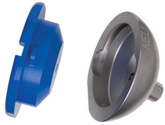
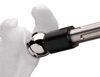
.png) The fancy cut protector
from the DePuy XTend reverse system shown
left may be used at the discretion of the surgeon. This device may
obstruct visualization of the glenoid but it allows
for the DePuy Xtend forked Homan to lever on the humerus with less
chance of
crushing it. The fancy cut protector
from the DePuy XTend reverse system shown
left may be used at the discretion of the surgeon. This device may
obstruct visualization of the glenoid but it allows
for the DePuy Xtend forked Homan to lever on the humerus with less
chance of
crushing it. |
|
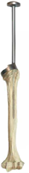
Humeral Reaming
Continue increasing reamer size until cortical bone chatter resistance is encountered.
Note that in the manufacture's technique image, the starter reamer and humeral reamers will breach the later humeral cortex if allowed to continue reaming in a direct inferior direction. Breaching the cortex should be avoided. |
Humeral broaching can be carried out now or after work on the glenoid is complete. Postponing broaching until completion of glenoid arthroplasty will decrease the occurrence of proximal humeral collapse during glenoid exposure.
Glenoid
.png) Use Homan and double Homan
(aka Playboy retractors and Forked Homans) retractors to expose the glenoid. Use Homan and double Homan
(aka Playboy retractors and Forked Homans) retractors to expose the glenoid. |
.png) Determine where the spine of the scapula is and stick the double Homan
retractor there to mark your spot. Determine where the spine of the scapula is and stick the double Homan
retractor there to mark your spot. |
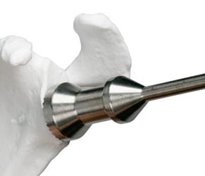
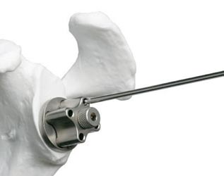
 Assemble the
Central Drill Guide by inserting and threading the Central Drill Guide
Handle in the corresponding plate hole (right or left depending on the
shoulder being operated upon). Assemble the
Central Drill Guide by inserting and threading the Central Drill Guide
Handle in the corresponding plate hole (right or left depending on the
shoulder being operated upon).
For right shoulders, the Central Drill Guide Handle should be placed in the 3 o'clock hole.
For left shoulders, the Central Drill Guide Handle should be placed in the 9 o'clock hole.
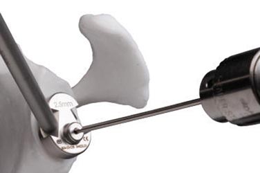
You can also mark you starting hole at 14mm from the inferior edge of the glenoid. Position the Central Drill Guide as low as possible so that its border follows the inferior edge of the glenoid.
The Central Drill Guide should be held perpendicular to the plane of the glenoid face to allow for a 10 degree inferior tilt. Make sure that the Central Drill Guide Handle is not tilted superiorly.
Use a 2.5mm drill bit either angled superiorly at 10 degrees or perpendicularly to the glenoid face (depending on fixation goals). This ensures that the glenosphere will either be perpendicular to the plane of the glenoid face or has a slight inferior tilt which may reduce the risk of scapular notching as well as decrease shear forces to the glenoid screws.
Ensure that the depth of the drill hole is approximately 30mm (length of the central screw on the baseplate). The surgeon may wish to feel the distal tip of the drill to ensure proper position and a bi-cortical path.
Note: If you are concerned about the getting the baseplate screw tip through the medial cortex of the glenoid, you can use the 3.2mm drill to make a larger hole than the 2.5mm drill. This will make is easier to get the baseplate center screw to bite is is the technique you will more likely use if working the Matsen. |
|
|
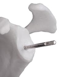 Leave the 6.5mm Guide Tap in the glenoid. |
|
The glenoid reamers come in 4 sizes: starter, small, medium, and large. The medium reamer will provide adequate clearance for a 36 neutral gelenosphere. A small may also work (in conjunction with a Baseplate Rim Planer) if the medium ream will not fit in the shoulder cavity.
Connect the medium-sized Glenoid Reamer to the Glenoid Reamer Driver for power use. Place the hole of the cannulated Glenoid Reamer onto the 6.5mm Guide Tap and begin to ream the glenoid surface using power. Ream to expose subchondral bone.
If you angled the central guide in superiorly, continue reaming to violate the subchondral bone on the inferior 50% of the prepared glenoid until bleeding bone is exposed.
Be careful not to over ream and to preserve the subchondral bone.
Remove the 6.5mm Guide Tap upon completion. Manual removal of the 6.5mm Guide Tap is achieved either by connecting the Quick-Coupling T-handle directly to the 6.5mm Guide Tap or by connecting the Manual Tap Driver Adapter to the Ratchet Handle. |
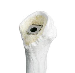
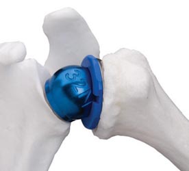
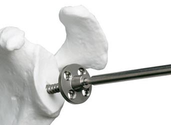 Implant
the Glenoid Baseplate into the prepared glenoid by purchasing the tip of
the 6.5mm central bone screw into the anterior cortex of the scapula for
secure fixation. Manual placement of the Glenoid Baseplate is achieved
by connecting the Ratchet Handle to the 3.5mm Hex Driver, which mates
with a hex feature on the Morse taper of the Glenoid Baseplate. Implant
the Glenoid Baseplate into the prepared glenoid by purchasing the tip of
the 6.5mm central bone screw into the anterior cortex of the scapula for
secure fixation. Manual placement of the Glenoid Baseplate is achieved
by connecting the Ratchet Handle to the 3.5mm Hex Driver, which mates
with a hex feature on the Morse taper of the Glenoid Baseplate.
When fully seated, the Glenoid Baseplate should sit flush with the glenoid, and the scapula should rotate slightly when attempting to tighten it down onto the glenoid surface. |
 The purchase of the central screw when the baseplate is fully seated MUST BE VERY SECURE so that the attempted further advancement of the screw will cause the entire scapula to rotate.
Ideally, screw holes will be located at the 12, 3, 6, and 9 o'clock positions to allow for max inferior and superior screw placement.
|
|
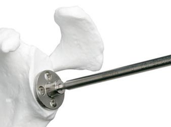
Drill your screw holes through the 3.2mm 4-hole Drill Guide perpendicular to the Glenoid Baseplate. Place free 3.2mm drills in two of your holes to prevent disengagement of the the Glenoid Baseplate and remove the 3.2mm 4-hole Drill Guide.
Remove your 3.2mm drills.
Measure the depth of each predrilled screw hole using the Depth Gauge. Install each 5.0mm locking screw at this point. Manual placement of the 5.0mm locking bone screw is achieved using the 3.5mm Hex Driver connected to the Ratchet Handle. Power placement of the 5.0mm locking bone screw is achieved by connecting the Power Tap Extension to the 3.5mm Power Hex driver.
Note: The new set has a two part drill guide with 4.0mm drills. This makes it easier to get the locking screw tips trough the medial cortex under the glenoid. This is currently the preferred technique on our service. |
|
Use a 2.5mm drill guide and drill to drill out the most inferior screw hole and any screw hole left without a locking screw. Measure the depth of each predrilled screw hole using the Depth Gauge. Install your non-locking screws.
Manual placement of the 3.5mm non-locking bone screw is achieved using the small 2.5mm Hex Screwdriver. Power placement of the 3.5mm non-locking bone screw is achieved by connecting the Power Tap Extension to the 2.5mm Power Hex Driver.
Note: If you used 4 locking screws in the previous step, you obviously will not use this technique for the inferior screw. |
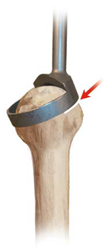
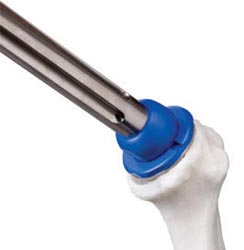
 Position
the Baseplate Rim Planer over the Glenoid Baseplate. Manually ream
around the rim of the Glenoid Baseplate to remove any bone or soft
tissue. This will help to prevent impingement when implanting the
Glenoid Head onto the Glenoid Baseplate. Position
the Baseplate Rim Planer over the Glenoid Baseplate. Manually ream
around the rim of the Glenoid Baseplate to remove any bone or soft
tissue. This will help to prevent impingement when implanting the
Glenoid Head onto the Glenoid Baseplate. |
You may trial your glenosphere at this time or wait until finalization of humeral preparation.
Humeral Finalization and Component
|
Attach the smallest size (6mm) Humeral Broach to the Humeral Broach Handle. |
|
Gently impact the Humeral Broach Handle using a mallet until the depth indicator line on the lateral side of the Humeral Broach Handle lines up with the lateral humeral cortex to ensure that the Humeral Broach has been countersunk into the metaphysis of the proximal humerus.
|
 Humeral
Socket Reamers are designed with cross-cut teeth to effectively prepare
a proximal cup of bone support that will surround the Humeral Socket.
They are available in three sizes: small, medium, and large. Humeral
Socket Reamers are designed with cross-cut teeth to effectively prepare
a proximal cup of bone support that will surround the Humeral Socket.
They are available in three sizes: small, medium, and large.
|
 Remove excess bone from the medial margin of the humeral metaphysis
using a burr or curved rongeur. Leave the final countersunk
Humeral Broach in the humeral canal while preparing the glenoid to
minimize the risk of deforming or fracturing the proximal humerus. Remove excess bone from the medial margin of the humeral metaphysis
using a burr or curved rongeur. Leave the final countersunk
Humeral Broach in the humeral canal while preparing the glenoid to
minimize the risk of deforming or fracturing the proximal humerus.
Final preparation of the proximal humerus will be performed after glenoid baseplate insertion. |
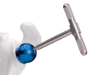
Trialing
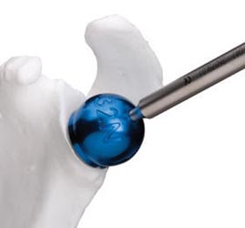 Glenoid
Head Trial sizes are available in six sizes: 32mm blue (neutral and -4mm offset), 36mm yellow (neutral and-4mm offset), and 40mm green
(neutral and -4mm offset). Glenoid
Head Trial sizes are available in six sizes: 32mm blue (neutral and -4mm offset), 36mm yellow (neutral and-4mm offset), and 40mm green
(neutral and -4mm offset).
We generally use a yellow 36 neutral.
Select the appropriate Glenoid Head Trial with the correct offset and position it onto the Glenoid Baseplate. The Glenoid Head Inserter is used to place the Glenoid Head Trial onto the Baseplate. The Glenoid Head Inserter should be impacted lightly to seat the Head Trial onto the Morse taper of the Glenoid Baseplate. |
 Use the Glenoid Head Impactor to provide a greater impaction force to the Head Trial and ensure that it is fully seated.
As the 36mm -4mm offset, 40mm neutral, and 40mm -4mm offset glenoid heads are hooded on the inferior portion, excess bone from the medial, inferior margin of the glenoid should be removed using a high speed burr or curved rongeur to ensure that the hooded glenoid head sits flush on the prepared glenoid without impingement.
|
 Humeral
Socket Shell Trials are available in three sizes: neutral, +4mm
thickness, and +8mm thickness. Socket Insert Trials are available in
six sizes: 32mm blue (standard and semi-contrained), 36mm yellow
(standard and semi-constrained), and 40mm green (standard and
semi-constrained). Note that the inner diameter of the Semi-Constrained
Humeral Socket Insert will have 10 degrees more articular arc than the
inner diameter of the Standard Humeral Socket, providing more articular
contact with the head for additional stability. Humeral
Socket Shell Trials are available in three sizes: neutral, +4mm
thickness, and +8mm thickness. Socket Insert Trials are available in
six sizes: 32mm blue (standard and semi-contrained), 36mm yellow
(standard and semi-constrained), and 40mm green (standard and
semi-constrained). Note that the inner diameter of the Semi-Constrained
Humeral Socket Insert will have 10 degrees more articular arc than the
inner diameter of the Standard Humeral Socket, providing more articular
contact with the head for additional stability.
The Socket Insert Trials assemble to the Socket Shell Trials by lining up the tabs of the Liner Trial with the scallops of the Shell Trial. A clockwise ¼ turn of the Liner Trial will lock the Liner Trial to the Shell Trial.
You may wish to impact a Humeral Socket Shell Trial onto a humeral broach to create a solid humeral trail. This decreases problems with the shell rotating and coming loose during trialing.
|
 If
you have not impacted the trial shell on the trial broach on the back
table, you can do so in situ. Position the taper of the Humeral
Socket Trial into the opening of the countersunk Humeral Broach to
ensure that it sits flush against the prepared metaphysis without any
impingement from osteophytes, labrum, or soft tissue. Use the
Humeral Socket Impactor to seat the Humeral Socket Trial onto the Morse
taper of the Humeral Broach. If
you have not impacted the trial shell on the trial broach on the back
table, you can do so in situ. Position the taper of the Humeral
Socket Trial into the opening of the countersunk Humeral Broach to
ensure that it sits flush against the prepared metaphysis without any
impingement from osteophytes, labrum, or soft tissue. Use the
Humeral Socket Impactor to seat the Humeral Socket Trial onto the Morse
taper of the Humeral Broach.
If you made a solid humeral trial on the back table, use the Humeral Socket Impactor to seat the humeral component in the humerus. |
 Reduce the shoulder by pulling laterally on the Humeral Socket Trial and
proximal humerus to clear it from the Glenoid Head Trial, while flexing
and internally rotating the arm, until a gentle, but appreciable,
“clunk” occurs. If the shoulder reduces too easily, soft
tissue tension is inadequate, and the Humeral Socket Shell Trial
with additional offset (+4mm and +8mm) should be considered as well as
an alternate glenoid head. If the shoulder cannot be reduced, there may
be soft tissue impingement, the patient may not be completely relaxed,
or additional reaming of the proximal humerus may be required. Reduce the shoulder by pulling laterally on the Humeral Socket Trial and
proximal humerus to clear it from the Glenoid Head Trial, while flexing
and internally rotating the arm, until a gentle, but appreciable,
“clunk” occurs. If the shoulder reduces too easily, soft
tissue tension is inadequate, and the Humeral Socket Shell Trial
with additional offset (+4mm and +8mm) should be considered as well as
an alternate glenoid head. If the shoulder cannot be reduced, there may
be soft tissue impingement, the patient may not be completely relaxed,
or additional reaming of the proximal humerus may be required. |
 Once
shoulder mobility and joint stability are sufficient, dislocate the
shoulder to remove all trial components. Once
shoulder mobility and joint stability are sufficient, dislocate the
shoulder to remove all trial components.
Rotate the Socket Insert Trial (poly trial) counter-clockwise and remove it from the Shell Trial. If the Shell Trial cannot be removed by hand, insert the Glenoid Head Distractor into the hole through the taper of the Shell Trial and rotate clockwise until the trial disengages from the Humeral Broach. |
 The Glenoid Head Distractor is also used to remove the Glenoid Head Trial. Position the Glenoid Head Distractor into the central hole of the Glenoid Head Trial and rotate clockwise until the Glenoid Head Trial disengages from the Glenoid Baseplate. After the trial components and the broach have been removed, clear any remaining debris from the humeral canal. |
Joint tensioning and stability assessment should be performed with particular care, using the following manufacture's guidelines:
If instability can be demonstrated, it is critical to identify the cause and develop a solution to the problem. Make sure that the implants have been positioned correctly with respect to the bone and to each other. Overcome any conflicts between the proximal humeral component and soft tissues or osseous structures that surround the glenosphere (e.g. non-union of the greater tuberosity) by excision of the conflicting elements. Inadequate tensioning may be overcome using:
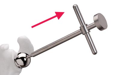
If unable to reduce the joint, the options include additional soft tissue releases and lowering the level of humeral resection. When the trials are satisfactory, the trial glenosphere should be removed using the extraction T-Handle so that final implant fixation can be performed.
Depending on space constraints, either the real glenoid or humeral components can be secured next.
Glenoid Component Emplacement
Glenoid Head Implants are manufactured with a wrought cobalt chrome articulating glenoid head surface and reverse Morse taper for fixation to the Glenoid Baseplate. Glenoid Heads are available in diameters of 32mm, 36mm, and 40mm, in either a neutral or -4mm offset. The 36mm -4mm offset, 40mm neutral (not hooded), and 40mm -4mm offset Glenoid Heads are hooded on the inferior portion. All Glenoid Heads have a 5.4mm diameter hole in the center of the glenosphere to accept a 3.5mm titanium alloy Retaining Screw that is 16mm long. Although the Glenoid Head is attached to the Glenoid Baseplate via a Morse taper connection, the Retaining Screw is designed to be tightened into the central part of the Glenoid Baseplate to provide an additional measure of security.
 Clear
any soft tissue around the circumference of the Glenoid Baseplate.
Irrigate the Glenoid Baseplate surface including the Morse taper and dry
thoroughly. Clear
any soft tissue around the circumference of the Glenoid Baseplate.
Irrigate the Glenoid Baseplate surface including the Morse taper and dry
thoroughly.
|
|
|
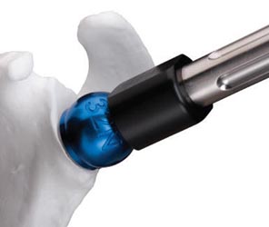
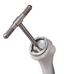
 This
is an optional step: Thread the Glenoid Head Inserter onto the Glenoid
Head implant and pull on the Glenoid Head Inserter to ensure the Glenoid Head is
fully seated onto the Morse taper of the Glenoid Baseplate. A fully seated
Glenoid Head implant will not move. This
is an optional step: Thread the Glenoid Head Inserter onto the Glenoid
Head implant and pull on the Glenoid Head Inserter to ensure the Glenoid Head is
fully seated onto the Morse taper of the Glenoid Baseplate. A fully seated
Glenoid Head implant will not move.
Note: Do NOT use a mallet for this step - as you can break the inserter threads off in the component.
|
 Insert
the 3.5mm titanium alloy Retaining Screw into the outer central hole of
the Glenoid Head. Tighten the Retaining Screw using the Torque Limiting
Driver. Insert
the 3.5mm titanium alloy Retaining Screw into the outer central hole of
the Glenoid Head. Tighten the Retaining Screw using the Torque Limiting
Driver. |
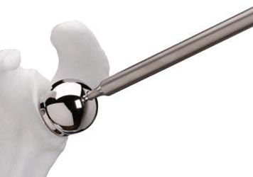
 Using the Glenoid Head Impactor,
re-impact the
Glenoid Head implant onto the Glenoid Baseplate implant using three firm taps. Using the Glenoid Head Impactor,
re-impact the
Glenoid Head implant onto the Glenoid Baseplate implant using three firm taps. |
|
Re-Tighten
the Retaining Screw using the Torque Limiting Driver. If the screw
turns at all, the glenosphere may not be fully seated. |
Humeral Component Cementing
Remove all trial cups and trial implants.
 Select
the appropriately sized Humeral Socket Shell. Position the Socket
Shell into the Humeral Stem/Socket Impaction Fixture. Select the
appropriately sized Humeral Socket Insert based on the last trial
reduction performed. Carefully align the Humeral Socket Insert
into the opening of the Humeral Socket Shell. Select
the appropriately sized Humeral Socket Shell. Position the Socket
Shell into the Humeral Stem/Socket Impaction Fixture. Select the
appropriately sized Humeral Socket Insert based on the last trial
reduction performed. Carefully align the Humeral Socket Insert
into the opening of the Humeral Socket Shell.
|
 Select
the appropriately sized Humeral Stem implant. Note that the Humeral Stem
implant should be smaller than the final Humeral Broach size used.
Position and lock the Humeral Stem into the Humeral Stem/Socket
Impaction Fixture. Select
the appropriately sized Humeral Stem implant. Note that the Humeral Stem
implant should be smaller than the final Humeral Broach size used.
Position and lock the Humeral Stem into the Humeral Stem/Socket
Impaction Fixture.
|
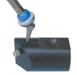
Determine the trial size of the cement restrictor and gauge the implantation depth. Check that the trial restrictor is firmly seated in the canal, then remove trial.
.png) Use pulsatile lavage and a nylon brush to clear the humeral canal of debris
and to open the interstices of the bone ready for the cement. Place the
definitive cement restrictor at the appropriate depth and check that it is
firmly seated in the canal. Use pulsatile lavage and a nylon brush to clear the humeral canal of debris
and to open the interstices of the bone ready for the cement. Place the
definitive cement restrictor at the appropriate depth and check that it is
firmly seated in the canal. |
If you have a subscapularis to repair, drill and fill 6 number 2 Tevdex suture through the proximal humerus near the lesser tuberosity to enable secure reattachment of the subscapularis (if possible). You may wish to avoid re-attachment if unable to externally rotate the humerus to zero degrees.
Irrigate the canal, during a secondary cleaning, using pulsatile lavage to remove loose bone remnants and marrow. Some surgeons may wish to insert a one-inch gauze pre-soaked in an epinephrine (1:1,000,000 solution) or hydrogen peroxide solution to aid haemostasis and the drying of the humeral canal.
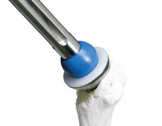
.png) Cement in the humeral implant as directed. We use 1.5 packs of Simplex
with 2 grams of Vancomycin. Cement in the humeral implant as directed. We use 1.5 packs of Simplex
with 2 grams of Vancomycin. |
 Introduce
the final implant in 30 degrees of retroversion in line with the long
axis of the humerus. Lightly tap the prosthesis into the humeral
canal using the appropriate Humeral Socket Impactor. Introduce
the final implant in 30 degrees of retroversion in line with the long
axis of the humerus. Lightly tap the prosthesis into the humeral
canal using the appropriate Humeral Socket Impactor.
|
Place pressure on the component with your thumb until the cement is fully polymerized to avoid micromotion that could cause crack propagation. Cement hardening takes about 10 minutes in the laminar airflow room and can be check by tapping on a test piece of cement.
Irrigate the wound thoroughly. Place the trial articular surface and reduce the joint. Confirm stability and dislocate the humerus.
Note: All junction surfaces between the implant components should be clean and free of any tissue before impaction. Reduce the joint and carry out a final assessment of joint stability and range of motion.
Reduce the joint and carry out a final assessment of joint stability and range of motion.
Closing
Secure the subscapularis if indicated and assess ER ROM.
Close the delta-pectoral interval loosely. If needed, emplace a drain over deltoid and exit skin a good 7.5cm or more away from incision site. Use staples to close the wound.
Postop
If iodine was used to prep the patient, this should be removed with alcohol immediately after dressing the incision site.
No CPM
Place Pt in sling
For PT - Axillary care and hand to mouth exercises.
Immediately post op, do a Grashey AP of the operative shoulder with arm in sling .
.png) The primary surgeon will mark the coracoid and a line from the coracoid down the deltopectoral interval. This interval can and should be palpated prior to marking.
The primary surgeon will mark the coracoid and a line from the coracoid down the deltopectoral interval. This interval can and should be palpated prior to marking..png)
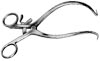 After incision through the dermis, two interposing
Gelpi retractors should be
used to separate the two skin edges and to pull them away from the muscle bed.
After incision through the dermis, two interposing
Gelpi retractors should be
used to separate the two skin edges and to pull them away from the muscle bed. The
humeral cut recommended by the designers is smaller than what we generally do of
conventional shoulder replacements and other reverse systems. The
recommended resection shoulder be no larger than a tablespoon.
The
humeral cut recommended by the designers is smaller than what we generally do of
conventional shoulder replacements and other reverse systems. The
recommended resection shoulder be no larger than a tablespoon.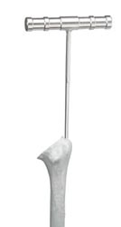
 Enter
the intramedullary canal where the supraspinatus tendon normally would attach to
the greater tuberosity lateral to the humeral head cut surface. You may need to
use a rongeur to make opening for the reamer. Begin reaming with the small
T-handle Starter Reamer and then advance with the 6mm Reamer.
Enter
the intramedullary canal where the supraspinatus tendon normally would attach to
the greater tuberosity lateral to the humeral head cut surface. You may need to
use a rongeur to make opening for the reamer. Begin reaming with the small
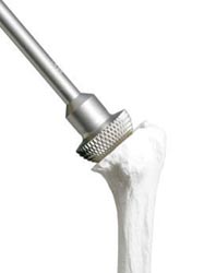
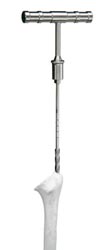
T-handle Starter Reamer and then advance with the 6mm Reamer.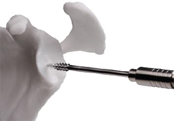 Seat
the 6.5mm Guide Tap in the same direction and angle
Seat
the 6.5mm Guide Tap in the same direction and angle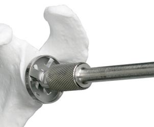
 Attach
the 3.2mm 4-hole Drill Guide onto the Glenoid Baseplate. Using the 3.2mm drill
bit, drill all holes intended for your 5.0mm locking screws. You may wish
to use a smaller non-locking screw at the 6 o'clock position or where you feel a
locking screw will have inadequate fixation.
Attach
the 3.2mm 4-hole Drill Guide onto the Glenoid Baseplate. Using the 3.2mm drill
bit, drill all holes intended for your 5.0mm locking screws. You may wish
to use a smaller non-locking screw at the 6 o'clock position or where you feel a
locking screw will have inadequate fixation.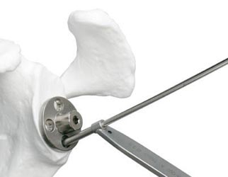
 The
Humeral Broaches are symmetrically designed and available from 6mm to 14mm
diameters in 1mm increments. Each Broach is supposedly precisely matched
with the Humeral Stems. To allow for an adequate cement mantle, a stem
smaller than the final broach size should be selected.
The
Humeral Broaches are symmetrically designed and available from 6mm to 14mm
diameters in 1mm increments. Each Broach is supposedly precisely matched
with the Humeral Stems. To allow for an adequate cement mantle, a stem
smaller than the final broach size should be selected. 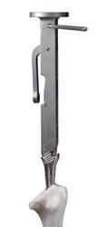
 As
a guide for proper alignment and retroversion, you can attach the Retroversion
Alignment Rod to the right or left hole in the Humeral Broach Handle.
Externally rotate the forearm, and align the Retroversion Alignment Rod parallel
to the patient’s forearm to maintain approximately 30 degrees of humeral
retroversion. We don't do this.
As
a guide for proper alignment and retroversion, you can attach the Retroversion
Alignment Rod to the right or left hole in the Humeral Broach Handle.
Externally rotate the forearm, and align the Retroversion Alignment Rod parallel
to the patient’s forearm to maintain approximately 30 degrees of humeral
retroversion. We don't do this.