CS 315 Homework 3 - CubeBot
Due Wed Oct 08 Fri Oct 10 at 11:59pm
Overview
In this assignment, you will be modeling and rendering a small scene made up entirely of 3D cubes. Your scene will center on a posed humanoid robot--a robot that you will be animating in the next assignment!

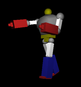
An example of a CG robot using cubes and spheres (by Dave Akers). Yours should only use cubes, and need not be quite this detailed.
In modeling this robot, you will have a chance to practice working with 3D transformations in OpenGL--and in particular with transformation hierarchies (creating series of transformations that can be used to easily describe characters with a "connected" body) as part of a "scene graph". You will also begin working with implementing ways to manipulate the "viewing" angle, as well as include more jQuery-based interactions
This assignment should be completed individually. You should not use any 3rd party libraries (check with me if you wish to).
Objectives
- Practice with 3D models and transformations in OpenGL
- Implement a hierarchical transformation system
- Practice working with the camera in OpenGL
- Practice implementing simple interactions in WebGL
Necessary Files
You will need a copy of the cs315-hwk3.zip file which contains the starter code for this assignment. The file structure is nearly identical to the last assignment; however, I've made a few notable changes:
-
The
cubebot.jsfile is where you should model your robot and draw your cubes (draw in therender()method, just like for the last assignment). -
I've refactored the OpenGL method calls (e.g., interactions between the shader, draw calls, etc) into a separate
cube_renderer.jsfile, encapsulating everything into a JavaScript class called aRenderer. This will let you focus on the modeling process for your robot; you will not need to modify the OpenGL code in thecube_renderer.jsfile.- You can draw cubes using the
renderer.drawCube(modelMatrix, color)method. This method takes as parameters amat4that is the combined model matrix modeling the cube to draw, as well as avec4(or 4-element array) representing the color in RGBA format. - Similarly, the
Rendererobject has an "instance variable" calledviewMatrixthat represents the view matrix. You'll need to work with this variable for the last part of the assignment; you can access it with dot notation.
- You can draw cubes using the
- The provided vertex shader is slightly more complex. It does some very simple lighting in order to help show the depth of your 3D model. We will talk about how the math works to calculate this in more detail later in the course. You will not need to modify the shader for this assignment.
Note that the zip file also contains a README.txt file that you will need to fill out.
Assignment Details
Note that this assignment is less specifically detailed than the last--the OpenGL stuff has been handled for you; mostly you're just working with transformations and coordinate frames at this point!
Designing CubeBot


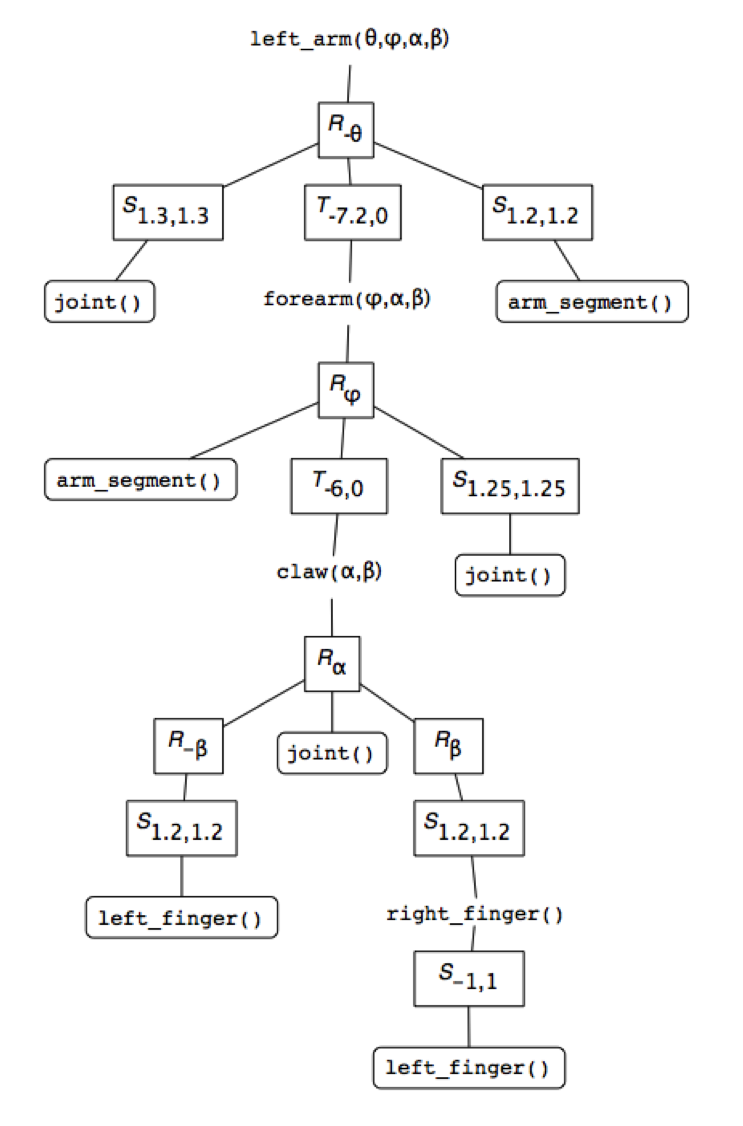
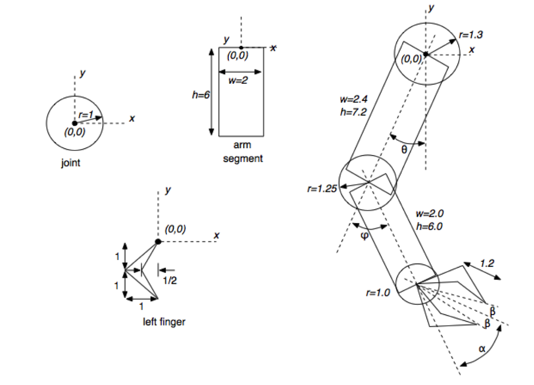
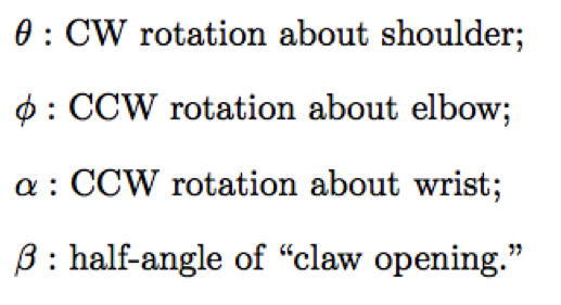
Figures by Wayne O. Cochran
Your robot will consist of several moving components: a torso, two two-segment arms, two two-segment legs, and a head (6 components total). Each upper arm will positioned relative to the reference frame of the torso, each lower arm relative to the reference frame of the corresponding upper arm, etc.
Your robot will be built from copies of a single basic primitive (provided for you): a cube. Cubes can be scaled and stretched into rectangles, and combined to produce more complex shapes.
- It's a good idea to start from a "paper" design of your robot (graph paper can be useful), to figure out what you want it to look like and where objects will need to be placed relative to one another. For example, you should think that "the left arm is translated A and rotated B from the torso", writing down those notes.
- Each local frame will need use as its origin a "pivot point"---you can think of these as the "joints" of the robot. By manipulating the pivot points, you'll be able to "pose" your robot! Keep this in mind as you plan out your robot.
- You are welcome to include additional components and details: small cubes to represent the "joints", cubes for facial features attached to the head (or elsewhere), hands with fingers, etc. Just be careful not to get bogged down! I strongly recommend starting out with the basics and then adding more details later.
- A note on size: the starter code displays a cube with vertices at (±1, ±1, ±1). The current viewing setup will "cull" any further away than -10 on the z axis, or closer than 10 on the z axis (which is the position of the camera). So your robot should fit within that grid. If your robot ends up being too big, you can scale down your coordinate system as defined in the torso, and it will apply to everything else.
Rendering CubeBot
After you've designed your robot, you'll need to model and render it in WebGL. Since robots are made up of cubes, you won't be modeling it in terms of vertex positions, but instead in terms of the transformations applied to each cube to put it into the proper position. Basically each piece of the robot will be represented by a different model matrix that applies to the cube--in particular, a transformation hierarchy of model matrixes, like we discussed in class.
-
You will need to specify a local frame transformation for each body part--that is, the transformation that gets from the parent's coordinate frame to the new local coordinate frame.
- Important: in order to support future additions, you should have the the "origin" of each body part's coordinate frame actually be at the "pivot point" between the current frame and the parent frame. So your origin for the arm's reference frame could actually be at the "shoulder" rather than at the center of the torso.
- Your torso should act as the root for the hierarchy tree!
-
You should create separate "drawPart()" methods to help organize your code; don't do all of your transformations/drawing inside the
render()method!- These methods may include multiple models (i.e., all the parts of the face, the arm and its bicep, all the fingers in a hand). You can think of position each of these models in terms of the "parts" coordinate frame (which is the one used in the main hierarchy).
-
In order to draw your robot, you'll need to traverse the transformation hierarchy tree. You transform your coordinate system into the correct frame, apply local transformations, draw what you want, and then move back out to the parent's frame to prepare for the next transformation. Using a post-order traversal, the basic algorithm we discussed in class (and what your helper methods might look like) is:
-
Set the transformation to the current coordinate frame (push current model matrix onto the stack)
-
You can easily "push" an item onto a JavaScript array using the
push()method. Note that this pushes onto the end of the array... butpop()removes from the end of the array, so it still functions like a stack! -
Vitally important!: You will need to store a separate copy of the current model matrix! Like Java, JavaScript is "pass-by-value", which means if you just push the current
mat4onto the stack, you'll actually be pushing a second reference to the same matrix, and any future modifications will apply to everything on the stack! -
You can easily make a copy of a
mat4using themat4.clone(a)method.
-
You can easily "push" an item onto a JavaScript array using the
-
Apply global transformations we want children to inherit to the current frame.
- Apply these transformations to the model matrix at the top of the stack.
- These transformations will primarily be rotations for your "pivot" points (see below)
- Draw each child component (post-order traversal). Call your other helper methods!
- Apply local transformations you do NOT want children to inherit (local rotations, translations, scales, etc).
- Draw this model's primitives. Note that this step may be mixed in with the previous if you have multiple cubes in each component.
-
Finally, restore your parent's model matrix by popping the current model matrix off the stack!
- This means that when the method returns and you move back up the tree, the parent will have its global transformations ready to go, as if there were no children!
Overall, each matrix on the stack represents the transformation to get to the coordinate frame of the robot's components following a post-order traversal of the hierarchy!
-
Set the transformation to the current coordinate frame (push current model matrix onto the stack)
- I recommend you model your robot in a very simple "pose" (i.e., standing still with arms at his sides)--you'll add in more complex posing in the next part of the assignment.
Posing CubeBot
Once you have your basic robot drawn, you should specify a "pose" for that robot.
-
A pose is represented by a collection of transformation matrices which are applied to each "pivot" point of the robot in determining the coordinate frame for that component (and by extension, all of its children!)
- These will usually be rotation matrices, though you may include a translation or scale component if your robot's arms detach or something. You should start with rotation matrices.
- These will be arbitrary rotation matrices though--a pose can involve rotation around any axis!
-
A pose should be stored as a JavaScript object, with the following structure:
{
  "torso" : mat4,
  "head" : mat4,
  "leftUpperArm" : mat4,
  "leftLowerArm" : mat4,
  "rightUpperArm" : mat4,
  "rightLowerArm" : mat4,
  "leftUpperLeg" : mat4,
  "leftLowerLeg" : mat4,
  "rightUpperLeg" : mat4,
  "rightLowerLeg" : mat4
}
I have included such an object for you at the top of the
cubebot.jsscript :) -
You should define a pose for your robot by filling the provided object with appropriate transformations, whic then get applied inside your drawing methods (as part of step 2 of the traversal algorithm).
-
You should compose the pose transformations inside your
init()method, rather than therender()method. It would make sense to have a helper method for this!
-
You should compose the pose transformations inside your
-
You should be able to swap out this pose with any other pose (e.g., created by other students) to put your robot into a different stance. I recommend sharing your pose functions on Piazza and trying it out :)
- In the next assignment, you will be modifying this pose object in order to animate the robot and make it dance!
Looking at CubeBot
At this point, you should have your modeled and posed robot rendering. However, it would be nice to be able to view your posed robot from different angles. For the last part of the assignment, add the ability to use the mouse of move the camera around the robot by clicking and dragging.
-
You will need to use jQuery events (like we did in lab) to track when the mouse moves. You'll be interested in the
.mousemove()
.mousedown()
and
.mouseup()
methods.
- It will be handy for later if you require the user to "shift drag"--that is, hold down the shift button while they drag (so that they can use non-shift drag for other interactions...). Recall you can use the .keydown() and .keyup() methods to determine when the shift key is pressed.
-
The basic idea is that when the user drags the mouse, you'll want to update the view matrix so that the transform representing the camera's position changes.
- You can access the
Renderer's view matrix variable asrenderer.viewMatrix. Just output any transformations back into this matrix and they will be applied to the rendering. - Because the view matrix initially models a camera translated back from the world frame's origin, you can simply apply rotations to this matrix to cause the camera to rotate around that origin! If your robot is centered at that point, you'll be able to look at it from different angles.
- You can access the
-
In order to make this rotation feel natural, you should implement what is called trackball rotation (see section 4.13.2 in the text). Basically you can imagine that there is an invisible "sphere" (of unit radius) sitting at the center of the screen; when you drag, you are "spinning" the sphere, and using those rotations to determine where to move the camera to. There are a couple of pieces to this:
-
First you need to determine how to map a point selected on a screen to a point on the invisible sphere. The way to do this is to consider the projection of the hemisphere you're dragging onto the
z=0plane (e.g., the screen). This means that the point{x,y,z}on the sphere is mapped to the point{x,y,0}... but because this is a hemisphere, it can be reversed, so that the point{x,y,0}maps to the point{x,y,z}, where \(\mathtt{z = \sqrt{1-x^2-y^2}}\).-
Note that your
{x,y}coordinates need to be normalized to be in terms of clip coordinates--e.g., between -1 and 1 (where -1,-1 is one corner and 1,1 is the opposite). In order to determine the points position on the canvas, you'll need to account for where the canvas is positioned on the page. You can do this using: -
Another update: in oder to make the math work, it looks like you'll need to scale these down further so that any point you select on the screen is "within" the unit sphere. Try scaling down by
(canvas.width+canvas.height)/4[values used by working THREE.js implementation]
  var x = evt.pageX - $('#glcanvas').offset().left
  var y = evt.pageY - $('#glcanvas').offset().top
-
Note that your
-
Given two points on the screen (e.g., the start and end points of the move), you can determine the axis and angle to rotate around by calculating the vectors \( \mathbf{v_0} = \mathit{P_0} - \mathbf{o} \) and \( \mathbf{v_1} = \mathit{P_1} - \mathbf{o} \)
(where \( \mathit{P_0} \) and \( \mathit{P_1} \) are the points on the sphere, and \( \mathbf{o} \) is the origin). The axis to rotate around is the vector normal to these (calculated with the cross product), and the angle to rotate by is equal to the angle between them (calculated using the dot product)!
- Remember to normalize the the vectors before taking their dot product! Alternatively, if your changes in position are very small, you can use the book's optimization and approximate the angle \( \theta \) with the magnitude of the cross product.
-
First you need to determine how to map a point selected on a screen to a point on the invisible sphere. The way to do this is to consider the projection of the hemisphere you're dragging onto the
- When implemented correctly, this should give you a natural-feeling interaction---it feels like you're grabbing a physical point on a sphere and dragging it around! Moreover, this should let you view your robot from any angle.
- Finally, you should modify the html file so that the instructions for the user interface are written below the canvas (e.g., "click and drag to move the camera"). You can put your instructions in a <p> tag.
In the end, your program should render your posed robot, and allow the user to drag the camera around to view your robot from different angles.
Extensions
There are a number of possible extensions to this assignment--some of which you'll be implemented in the next assignment! If you finish early (and the description is online), I recommend you start on that assignment next.
As another possibility: one of the issues with trackball rotation is that moving from \( \mathit{P_0} \) to \( \mathit{P_1} \) and then from \( \mathit{P_1} \) to \( \mathit{P_2} \) doesn't give you the same rotation as moving directly from \( \mathit{P_0} \) to \( \mathit{P_2} \). As a fix for this, you might look up and implement an arcball rotation.
Additionally, achieving smooth rotations is more effective with quaternions in place of matrices. We'll go over these in more detail for the next assignment, but you might look them up and see how to integate them into your assignment!
Submitting
BEFORE YOU SUBMIT: make sure your code is fully functional! Grading will be based primarily on functionality. I cannot promise that I can easily find any errors in your code that keep it from running, so make sure it works.
Upload your entire project (including the lib/ folder) to the Hwk3 submission folder on vhedwig (see
the instructions
if you need help).
Also include a filled-in copy of the
README.txt
file in your project directory!
The homework is due at midnight on Wed Oct 08 Fri Oct 10.
Grading
This assignment will be graded out of 19 points:
- [2pt] Your program displays your robot, which has been modeled from colored cubes
- [3pt] Your robot model has the requisite components (torso, head, two upper/lower arms, two upper/lower legs)
- [5pt] Your robot is modeled using a hierarchical transformation tree.
- [2pt] Your robot can be posed using a JavaScript object of the specified format.
- [1pt] Your displayed robot has been posed
- [1pt] The user can rotate the camera via the mouse
- [2pt] The camera is rotated using trackball rotation
- [1pt] Your HTML file includes details on how to control the camera/program!
- [1pt] Coding style (e.g., good use of helper methods, comments, etc)
- [1pt] README is complete