Austrans
Austrans is a small vehicle, automated transit system that is under development in Australia. The concept uses vehicles the size of a minivan that provide seating for up to 9 passengers. Austrans vehicles will be operated on narrow gauge steel rails supported on dedicated guideways either elevated, at grade or underground. Ground-level off-line stations are envisioned for all guideway configurations. The essence of the Austrans concept lies in the combination of the better features of PRT and GRT with operation at substantially higher speeds than either. Service would be scheduled during peak- periods and would be demand-responsive (taxi-like) during the remaining hours of the day.
Austrans is believed to be more economic than PRT because of its greater seating capacity. Its proponents argue that it would provide much more efficient loading of the guideways that would PRT. They also believe that rail technology offers significant advantages over rubber tires in terms of speed, stability and guideway costs. Rail also has some disadvantages (poor cornering, poor wheel/rail traction, operating noise) and the Austrans concept has been designed to overcome them. During the past five years, four patented concepts have been developed that will overcome these disadvantages, namely: (1) a self-steering bogie, (2) grip wheels, (3) a Z-rail section and (4) a high speed switch.
The self steering bogie enables negotiation of curves down to an 8 meter radius without reliance on flange contact and provides stable operation at speeds up to 120 kph. It also reduces noise considerably. To overcome the low traction obtained from steel wheels/rail contact, ancillary wheels are designed to run along the underside of the rail head and increase the traction available for vehicles to climb grades up to 20% and to provide emergency braking of 0.8g. The Z-section rail is necessary to allow the self-steering bogie to operate properly. The running faces of the rail are inclined inwardly at 20 degrees to match the bogie wheels. A high speed switch is seen as essential for operation of vehicles at close spacing. A flexing switch arrangement has been designed that would be actuated by stored hydraulic power. The ties are pivotally connected to the Z-rails and are supported at their ends both vertically and laterally in either setting of the switch. The ties also support a flexible, inverted power rail and communication conductors so that all move in unison with the rails. The mechanism banks the rails in a branchline setting, so allowing higher speeds to be used.
Extensive consideration was given to the selection of the Austrans vehicle size. A 9-passenger vehicle is proposed as this gives the best compromise between economical off-peak services, on-demand operation and low manufacturing costs. Studies have shown that the 9-seat vehicle operating in commuter corridors can provide one-way line capacities up to 9,000 passengers per hour - and more, if vehicles are linked in pairs. The vehicle is 5.4m in overall length, 1.9m wide and 2.25m high from rail head level. Diagrams of the vehicle are shown below. The body would be fibreglass or pressed aluminum panels covering an aluminum or steel frame. The pair of main wheels on each bogie would be driven by an AC electric motor supplied with power from individual computer controlled inverter drives. A computer on-board each vehicle would control the starting, acceleration and stopping of the vehicle by sending commands to the motor controllers and braking systems. These vehicle-based computers would communicate with the central control system by way of a leaky co- axial cable laid in a duct placed between the Z-rails.
![[vehicle diagram]](aust3.jpg)
![[vehicle diagram]](aust4.jpg)
The Austrans guideway is designed for installation in a variety of situations and can be elevated, at-grade or in tunnel. All configurations would be totally grade-separated and the narrow gauge rails (750mm) and small vehicles would dictate minimally sized structures. The supporting structures would generally be of precast concrete, factory built and erected on foundations on site. Spacing between track centerlines would be 2.2m on dual track guideways, providing an overall dynamic corridor 4.1m wide. It is estimated that Austrans tunnels will have a cross-section area 36% the size of conventional heavy rail tunnels.
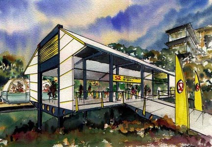
Three types of stations are envisioned: off-line, on-line and high capacity. All off-line stations would be at ground level since the vehicle can climb grades, thereby avoiding the cost and passenger inconvenience of stairs, escalators or elevators. The standard station would have a two-berth configuration and could accommodate up to 1000 passengers per hour in each direction. Smaller, on-line stations are envisioned for locations where traffic is light and would be similar to a bus stop. When high passenger volumes are anticipated, stations would have multiple loading bays to allow for vehicle dispatch to separate destinations. Intending passengers will indicate their destination at the time of ticket purchase, which will provide the control system with real-time traffic demand for the whole network and enable it to decide on an appropriate mix of itineraries to meet the traffic demand at any one time. For most passengers during the peak period, some enroute stops would occur. During off-peak periods, non-stop travel to the destination would be more frequent. The central control system would adjust the number of vehicles in use on a network to meet the demand by taking vehicles from or to storage areas placed at strategic locations. Passenger safety and security systems would be provided as would a backup anti-collision device that will stop the vehicle if the headway falls below a specific minimum. Click here to see an illustration of an Austrans station.
Development of the Austrans technology began in earnest in 1990 with an extensive review of existing work in the field of automated people movers and PRT systems. In 1993, Sinclair Knight Merz Pty Ltd, one of Australia's leading multi- disciplinary consulting firms, was commissioned to examine the feasibility of Austrans.
In July, 1998, work was initiated on a 0.5 km test track located in Sydney (Chullora), Australia. The first track of its kind features inclined rails, and tight radius curves, including an 8 meter radius turn through 180 degrees. The track features two switches and 1 in 5 grades servicing an elevated section.
The high speed switch is mechanical in nature. Vehicles will be operated with a 2.5 second headway at 70 km/h. Off-line stations will be used to permit non-stop station-to-station service.
The first full-size self-steering bogie has been completed and used for testing purposes. It is now part of the P1 test vehicle which was installed in September 2000 and is the culmination of 16 months of additional design, manufacture and assembly work. The P1 vehicle incorporates the Austrans passenger module and includes its interior features. Key steering and rail-gripping features of Austrans have now been demonstrated. Vehicles will be powered via a third rail.
Austrans was developed by Bishop Austrans, under the leadership of Managing Director, Laurie Bishop. Austrans have successfully gained a Federal R&D Start Grant of $14.3 million (AUS) which will ran through to February 2004.
A gallery of outstanding computer-generated images and sketches shows how Austrans could be fit into a variety of locations in the existing urban structure. An Austrans Newsletter is now being published every six months. The July 2001 issue is now available.
The official Austrans website is not longer available. This invention is not now being worked on.

Last modified: August 02, 2014