The purpose of this project is to build an application engine that simulates a GPOS scheduler. The application should be modular enough to allow the 'plug-in' of alternative scheduling algorithms.
This assignment will provide you with an opportunity to build a simulator engine that will provide a user with ways to test various scheduling approaches. But more importantly this will test your understanding of what goes on insofar as how the operating system coordinates the activities of multiple processes running concurrently. When this simulation is running you should be able to see the various processes running at different times and get out of sync such that the race condition is at work.
Note that this project should be done in C using pthreads to get the most out of it. If this proves logistically infeasible let me know well in advance and I will assess your work in Java as a substitute.
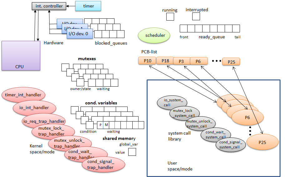
This diagram contains all of the various components that you will be simulating.
This will be a very high-level simulation that will only be working on action sequences and not details of those actions. For example, the simulated CPU will NOT be like the SimpComp or LC3 simulators where the CPU actually simulated execution of instructions. In this simulation the CPU is just a device that ticks off CPU cycles (counts) where each count represents some instruction in the process running. Each IO device will just be a single thread that ticks off a random interval count that throws an interrupt signal that is caught by the CPU thread. The timer is just a downcounter that throws an interrupt signal also, but on a regular time quantum basis. Processes are nothing more than a data structure that contains some data, including how many time ticks the program has before it starts repeating its instructions (like it is a big loop). More details below.
The simulator engine should be invoked from a command line with passed parameters. The parameters passed to the program will be the number of the processes (a pre-assigned menu of processes - see below), the order to initialize and start them, and the number of total time ticks to run the simulation. As the program runs the user should be able to press certain keys to cause interrupts to occur. Processes will have programmed system requests, such as for an I/O service, that will cause the scheduler to put them in the blocked state and in the waiting queue for that service. A random number generator can be used to determine the time that any service takes to complete and generate an interrupt.
The simulation run will print a string of text messages indicating which process is running, when it generates a service request, when an interrupt occurs, when a context switch occurs, and the state of each process on each context switch.
The simulation should include the following objects.
Create a process ADT that can be extended to simulate different kinds of processes. You should have a user interface process (e.g. one waiting for keyboard input), a calculating process (possible background job), and two processes that require inter-process communications, such as a producer-consumer pair. Each process should be an endless loop that doesn't really do anything (except the producer and consumer) but generates a service request, either for I/O or for inter-process communications & synchronization (e.g. mutex lock). The I/O requests don't really need to do any I/O, they just activate an I/O module that then generates a random time to assert an interrupt.
A process structure might look like this:
typedef struct process_str {
	int proc_type       // code for process type, e.g. 0=compute, 1=i0, 2=keyboard, etc.
	int	no_steps;		// number of time steps before resetting to 0 - number of instructions
	int no_requests;	// number of requests that will be generated during the process run
	int * requests;		// an array of requests, each request (e.g. io service) is issued at a specific
						// time step. These are the synchronous events that result in traps being issued.
						// You can get fancy and make this an array of RequestTypeStr which contains the
						// step number when issued, and a request type (e.g. 0=io, 1=sync, etc.)
} ProcessStr;
There are five different kinds of processes. A compute-bound process does not require I/O services, it just needs the CPU. An I/O-bound process requests I/O services periodically while it is running. You should have no more of these in the simulation than there are I/O devices and do not expect any one process to request more than just one type of device. This will avoid deadlock possibilities. There should be exactly one keyboard process. This process blocks waiting for a key input. Finally there should be one or more pairs of producers and consumer processes. These are to use the condition variables and mutexes to synchronize. The producer can simply calculate a number in sequence and then request to write it to the shared memory location. The consumer reads the value when it is signaled and prints it to the console. These two will implement the syncronization algorithms as depicted in Sample Program #5 in the book. You may want to increase the kinds of process running or increase the mixes, but be careful to not create a potential deadlock situation.
Each process should have an associated process control block with a minimum amount of information for the scheduler to manage. Process instances should be generated dynamically at start up. For example:
typedef struct pcb_str {
	int	pid;
	int next_step;		// this is the step count that the CPU had gotten to when this process was
						// prempted (like a PC register value)
	int state;			// e.g. 0=running, 1=ready, 2=interrupted, 3=blocked
	ProcessStr proc;    // pointer to the actual process
	int waiting_on;		// which queue is it in if it is waiting on something (blocked)
	int owns;			// which mutex lock does it own
	// anything else you need
} PCBStr;
You can use an array of these for your process control list with the pid number being the index in the list array.
The CPU object is the main loop that "runs" the running process. This is basically a loop that counts a number of steps (machine instructions) modulo some number between 1,000 and 10,000 (do experiments!). That is the counter loops back to zero at some point. Each process should have a different number within the range, randomly generated at startup, that it passes to the CPU to indicate the count at which a system call is made. Different processes should have different points in their count where the calls are made. The count represents the execution address so that if an interrupt occurs, that value is stored in the PCB while the interrupt is serviced.
The CPU doesn't actually do much during an interrupt service. It has to save the state of the currently running process (don't worry about simulating stacks in this version) and start running an interrupt service routine. The results of the routine will depend on what kind of interrupt is being serviced. If it is a timer interrupt then the CPU needs to simulate the timer interrupt, which, in turn, calls the scheduler and that does a context switch. There is no single right way to manipulate the data here, but the simulation should clearly demonstrate that a timer interrupt (using a time slice preemption model) causes a new process to get to run. Don't forget to instantiate an idle task (do nothing loop) and make sure it is always available in the ready queue,
The CPU can be simulated as a busy loop that increments the current process's PC and then checks to see if the current count causes any requests to occur. If so, the CPU has to save the state and run the appropriate request system call. In actuallity the system calls can just be simple helper functions or even part of the CPU in a switch statement. That is left to you to decide. However you do it, the trap service routine should manipulate the appropriate data structures (PCBs, blocked queues, etc.) and then call the scheduler as with the interrupt processing.
Create two internal I/O devices (e.g. simulated disk and video) that will get activated by a system call from one of the I/O-bound processes and then, at some random interval later, generate an interrupt when the service is complete. They don't have to actually do anything but they need do to generate an explanation string when they are activated and when they generate the interrupt.
You also need to have a keyboard I/O device that generates an interrupt whenever the user types a key.
The system timer is an autonomous device that has a standard time delay set after which it generates an interrupt. Since the timer has the highest priority of any interrupt you will have to make provisions for dealing with multi-level interrupts (just in case). For purposes of this simulation we can set all process quanta to the same value and use a simple thread_sleep for the timer. When it wakes up, it just generates the interrupt to the CPU. (BTW, there is no need to simulate the Programmable Interrupt Controller shown in the diagram).
All of these manage their respective queues and transfer process out of blocked states to the ready queue as appropriate. All will call the scheduler/dispatcher before returning. The main trick here is going to be the context switching needed for timer interrupts and io_requests. Remember this is just a simulation that is supposed to behave like the OS so don't get hung up in trying too hard to emulate the system stack handling. You can find a simple way to simulate what happens when a process is blocked or put back on the ready queue and a new process is selected for running.
These can be set up at initialization based on the nunmber of processes that need to communicate/synchronize. Create an object that keeps the current owner id and a queue of process ids (pointer) waiting on the mutex.
Implement these as discussed in the textbook (page 551 in my book). Initialize with as many as you are running producer-consumer pairs. This requirement is above and beyond what I have done in the past on this project and the purpose of this extra challenge is to use your solution in place of a final exam.
Make provisions for shared memory slots, as many as you have producer-consumer pairs.
The scheduler/dispatcher will be called each time an interrupt or a process makes a system call. It will need to determine what happened to activate it and then do whatever context switching is needed to enforce the round-robin policy. In the simple version, all processes have the same priority.
While the simulation is running we should see a running listing on the screen of which process is currently running, and a listing of all of the blocked queues (I/O, mutexes, and condition variables). When a timer interrupt or I/O service request occurs this should be printed on the next line (scrolling) and a message indicating the context switch that occurs is printed. You may need to put the CPU to sleep for a pause in order to have some time for a user to read the messages as they are printed. The run should look something like this:
P3 - running
I/O1 - P2, P5 waiting
M1 - P6 owns, P7 waiting
K - P13 waiting
CV1 - Cond 0, P1, P9 waiting
---------------------------------
Timer interrupt
P3 returned to ready queue
P1 selected from queue
P1 - running
For testing purposes you can redirect the the video output to a file so that you can check to see that things are working as expected.
If the simulation is done correctly you should get a different trace of events each time you run it with exactly the same number and kind of processes. This is because of the asynchronicity of the environment (e.g. keyboard input and I/O random time completions).
When the program is started you will give it a set of command line arguments that will designate how many and what kinds of processes you want to be running. There must be at least one keyboard input process, one compute-bound process (make this type your default fill-in process if you want to have more processes running than you specify in the command line - see below), one I/O-bound process, and one pair of producer-consumer processes. However you may run as many of these kinds as you want. In your readme.txt file be sure to include the “worst-case” scenario that you tested and if any such scenario blew up or got locked up somehow. The command line invocation should look like this:
$./scheduler -p 22 -k 2 -io 3 -pc 3This specifies a total of 22 processes, two of which will be keyboard, three will be I/O-bound, there will be 3 pairs of producers-consumers, and the rest will be compute-bound.
On startup the program should print a summary of the processes and their types and then a message indicating the start of the simulation (you can optionally time-stamp the start and end times if you are curious). After the simulation is running the above running messages are printed.
The points for this project will be 300 total. An additional 100 points as noted below.
The application should be named "scheduler.exe" (see below for exceptions). You need to write a README.txt file explaining the command line invocation and parameter requirements, e.g. ./scheduler -p 8 -pc 2 -c 24000 [eight total processes 2 producer-consumer pairs, 24000 total cycles]. Give full explanations for how to use this program as you have written it. Include your worst-case scenario testing.
Zip up your source files, executable file, resulting data file(s), and the README.txt, and turn them in via the Moodle site. Only one person on the team should do the turn-in for the project. I will provide grading to everyone on the team. A second upload link will be provided for each student to turn in a text file describing their contribution and evaluation of other team members
DUE DATE: Thr. June 6, 2013 23:55 — DEMO in class that day. NO LATE SUBMISSIONS
Additional Special Note: If your team dynamics are not working out you should report this to me as soon as possible. I do not want you coming in when the program is due or after and tell me that your teammates weren't doing their share, or some other sob story. I will give all team members the same grade regardless of contributions under the assumption that you have worked out your dynamics and are working well. If you come to me in a timely fashion with a problem I can help resolve it. And I can make grade adjustments between team members accordingly. But if you fail to communicate with me on issues, your grade may suffer in the end. It doesn't need to be that way!