 a) the
radius of curvature of the strip caused by T.
a) the
radius of curvature of the strip caused by T.Problem 5.26
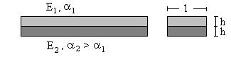
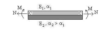
Welded bimetallic strip subjected to constant temperature increase T. Properties as shown. Determine
a) the
radius of curvature of the strip caused by T.
b) the maximum stress occurring at the interface.
c) the temperature increase that would result in the simultaneous yielding of both elements.
Two solution procedures are presented below:
Procedure 1: The two component strips are isolated, a free thermal deformation is allowed to take place, then forces are applied to reestablish geometric compatibility between the two strips. Governing equations are formulated, and two solution methods are presented: The force method and the displacement method.
Procedure 2: The strip is fixed against axial deformation, while the temperature increase is applied, and the stresses and end restraining forces are determined. The end restraining forces are then applied in reverse sense, and the stresses are determined by treating the strip as a beam of two materials. The final stresses are obtained by superposition.
I. Procedure 1 - Superposition to the State of Free Thermal Deformation
1) Separate the two strips and allow free thermal deformation
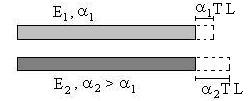
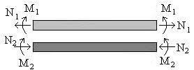
2) Apply self-equilibrating forces and moments at the ends of the strips to re-establish continuity of deformation at the interface
The resulting deformation is as shown below

The preceding formulation assumes that relaxed boundary conditions are acceptable at the strip ends.
Governing Equations
Equilibrium: Resultant force and resultant moment on a cross-section are zero:
N1 - N2 = 0 (1)
M1 + M2 - ( h/2)(N1 + N2) = 0 (2)
Geometric Continuity: The two strips must have the same curvature k, and the same interface strain e.
Constitutive Equations for strip 1
k = M1/E1I1= 12M1/E1h3 (3)
At the interface,
s1 = N1/A1 + M1h/2I1 = N1/h + 6M1/h2 (4)
e = a1T + s1/E1 = a1T + N1/E1h + 6M1/E1h2 (5)
Constitutive Equations for strip 2
k = M2/E2I2 = 12M2/E2h3 (6)
At the interface,
s2 = - N2/A2 - M2h/2I2 = - N2/h - 6M2/h2 (7)
e = a2T + s2/E2 = a2T - N2/E2h - 6M2/E2h2 (8)
Eq. (1), (2), (3), (5), (6), and (8) form a system of six equations in the six unknowns: N1, M1, N2, M2, e, and k, and Eq. (4) and (7) serve to compute s1 and s2.
Solution by the Force Method
To solve the system of equations (1) to (8) by the force method, we need to eliminate e and k. To do so, equate the two expressions of k in Eq. (3) and (6), and the two expressions of e in Eq. (5) and (8). Obtain, after simplification,
M1/E1 - M2/E2 = 0 (9)
(a1 - a2)T + (N1/E1h + N2/E2h) + 6(M1/E1h2 + M2/E2h2) = 0 (10)
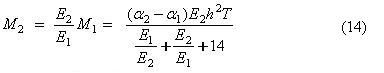
Eq. (1), (2), (9), (10) are now solved for N1, N2, M1, and M2. Using Eq. (1) and (9), Eq. (2) and (10) may be expressed in terms of the two unknowns, N = N1 = N2, and M1. Obtain, after simplification,
(1 +E2/E1)M1 - hN = 0 (11)
12(E2/E1)M1 + (1 + E2/E1)hN + (a1 - a2)E2h2T = 0 (12)
Eliminating N,
(1 + E2/E1)(Eq. 11) + (Eq. 12) = [(1 + E2/E1)2 + 12(E2/E1)]M1 + (a1 - a2)E2h2T = 0
Thus
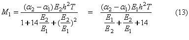
Eq. (9) yields
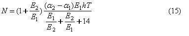
Eq.(11) yields
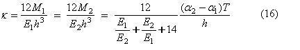
Eq. (3) and (6) yield
and Eq. (4) and (7) yield
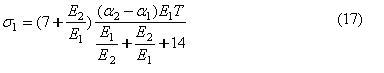
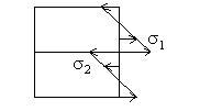
Comparing the two expression above, it is seen that the maximum stress in magnitude occurs in the material having the larger modulus of elasticity.
Part (c): temperature increase that would result in the simultaneous yielding of both elements.
Let s1Y = yield stress of material (1)
Let s2Y = yield stress of material (2)
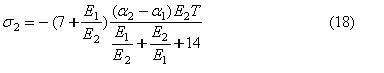
If the two materials yield simultaneously, the temperature TY at which this occurs must satisfy Eq. (17) and (18). Taking the ratio of s1/s2 at yield, we obtain
s1Y /s2Y = (7E1 + E2)/(7E2 + E1) (19)
Assuming Eq.(19) is satisfied by the material properties, TY is obtained from either Eq. (17) or (18).
The intent of the question is probably to find the temperature increase at which both strips have yielded. To do so, assume that yield starts in one of the strips, say in strip (1), at a temperature increase T1. For increasing T, a plastic zone develops in strip (1) near the interface until the stress at the interface in strip (2) reaches the yield stress for material (2).
Solution by the Displacement Method
To solve the system of equations (1) to (8) by the displacement method, we solve Eq. (3), (5), (6), and (8) for N1, M1, N2, M2, in terms of e and k, and substitute into the equilibrium equations, Eq. (1) and (2). Equivalently, if we had in mind to use the displacement method, we could have written the four equations mentioned above directly in the desired form, as shown below:
M1 = E1h3k/12 (3')
M2 = E2h3k/12 (6')
N1 = E1h(e - a1T) - E1h2k/2 (5')
N2 = - E2h(e - a2T) - E2h2k/2 (8')
Substituting into Eq. (1) and (2) yields, after simplification,
(E1+ E2)e + (E2- E1)hk/2 - (E1a1 + E2a2)T = 0 (20)
(E2 - E1)e + 2(E1+ E2)hk/3 + (E1a1 - E2a2)T = 0 (21)
It may be verified that eliminating e from Eq. (20) and (21) yields for k the solution found above in Eq. (16).
Instead of solving for e, and then computing the stresses at the interface, we can solve Eq. (20) and (21) directly for s1 = E1(e - a1T) and s2 = E2(e - a2T), as shown next.
Eq.(20) - Eq.(21) = 2E1(e - a1T) - (hk/6)( 7E1+ E2) = 0
Eq.(20) + Eq.(21) = 2E2(e - a2T) + (hk/6)(7E2 + E1) = 0
The solution of these two equations for s1 = E1(e - a1T) and s2 = E2(e - a2T) coincides with that found in Eq. (17) and (18).
II. Procedure 2 - Superposition to the Fixed State
1) Restrain
the axial deformation of the strips, while the temperature increase is applied,
and determine the stresses and the external restraining forces.
2) Apply in reverse sense the restraining forces, and determine the stresses treating the strips as a beam of two materials.
3) Superimpose states (1) and (2).
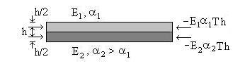 1) In the
fixed state, the strips have the stresses,
1) In the
fixed state, the strips have the stresses,
s1F = -E1a1T (22-a)
s2F = -E2a2T (22-b)
The axial forces at the ends are
N1F = s1F h = -E1a1Th (23-a)
N2F = s2F h = -E2a2Th (23-b)
2) To treat the strips as a beam of two materials, we first locate the weighted centroid C of the section. With origin at the interface, the y coordinate of C is given by (E1h + E2h)yc = E1h2/2 - E2h2/2, or
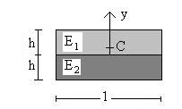 yc
= h(E1 - E2)/2(E1 + E2)
(24)
yc
= h(E1 - E2)/2(E1 + E2)
(24)
The axial and bending rigidities of the strip are
(EA) = E1h + E2h = (E1 + E2)h (25)
(EI) = E1I1 + E2I2 = E1(h - yc)3/3 + E2(h + yc)3/3 - E2yc3/3
This simplifies to
EI = h3*(E12+14E1E2+E22)/12(E1+E2) (26)
The strip is subjected at each of its ends to -N1F and -N2F. The resultant force and moment at C, at each of the ends, are
 N =
-N1F -N2F = (E1a1+
E2a2)Th
(27)
N =
-N1F -N2F = (E1a1+
E2a2)Th
(27)
M = (h/2 - yc)N1F - (h/2 + yc)N2F
This simplifies to
M = E1E2Th2(a2-a1)/(E1+E2) (28)
Using stress formulas for a beam of two materials, we have for the stresses at the interface,
s1(2) = E1N/EA + E1Myc/EI (29-a)
s2(2) = E2N/EA + E2Myc/EI (29-b)
3) Superposition of states (1) and (2) yields
s1 = s1F + s1(2) = -E1a1T + E1N/EA + E1Myc/EI (30-a)
s2 = s2F + s2(2) = -E2a2T + E2N/EA + E2Myc/EI (30-b)
Substituting for N, M, EA, EI and yc yields after simplification the same results as found by the previous method.