CEE 220 - INTRODUCTION TO MECHANICS OF MATERIAL
Tutorial Session 3
Topics: Stress-Strain Relations. Axially Loaded Members.
Learn the terminology and the graphical representation of
stress-strain relations.
Learn Hooke's law and the meaning of Poisson's ratio.
Integrate in a given problem the application of the three fundamental concepts
of mechanics:
Statics. Geometry of Deformation. Force-Deformation
Relations.
Recognize statically determinate and statically indeterminate problems, and
apply the
fundamental concepts in each case.
Include the effect of temperature in the axial force-deformation relation.
Stress-Strain Relations. Hooke's Law. Poisson's Ratio
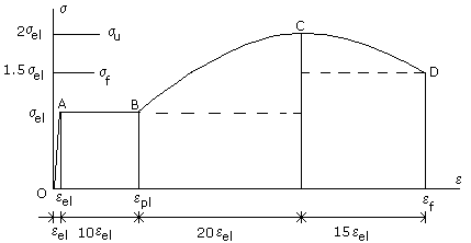
1. Draw a stress-strain diagram to represent the behavior outlined below. Before starting, read further down in order to choose an appropriate scale.
a) a linearly elastic part from the origin O to point A.
b) a perfectly plastic part AB whose plastic flow has a strain range equal to 10 times the elastic one.
c) a parabolic strain hardening part BC and a necking part CD characterized by the following:
c1) an ultimate stress equal to twice the elastic limit.
c2) a fracture stress equal to one and a half times the elastic limit.
c3) a strain hardening range equal to twice the plastic flow range.
c4) a necking range equal to one and a half times the plastic flow range.
2. Let the elastic limits for stress and strain in the
graph of question 1 be s = 200 MPa and
e = 0.001, respectively.
a) Determine the modulus of elasticity.
b) Is "Modulus of Elasticity" synonymous with "Young's Modulus"?
E = s/e
= 200/0.001 = 200,000 MPa or 200 GPa
c) Determine the modulus of resilience = Area under the elastic part of the
curve..
ur = seleel/2 = 200MPa (0.001 m/m)/2 = 0.1 MJ/m3
d) Determine the modulus of toughness = Area under the curve up to the fracture point. Note that the area under a parabolic segment symmetric about the axis of the parabola is equal to two thirds of the area of the rectangle constructed on the base and height of the segment.
ut = seleel/2 + sel(10eel) + sel(20eel) + (2/3)sel(20eel) + 1.5sel(15eel) + (2/3)(0.5sel)(15eel)
= seleel(0.5 + 10 + 20 + 40/3 + 22.5 + 5) = 71.33seleel = 142.67ur = 14.27 MJ/m
e) What is approximately the energy expended to perform a tensile test up to fracture of a specimen having a gauge length of 30 cm and a diameter of 5 cm? Recall that a Joule = 1 N.m.
Volume = V = 30p(25/4) = 589.05 cm3 = 589(10-6) m3
Energy expended = utV = 14.27 MJ/m3 [589(10-6) m3] = 0.0084 MJ or 8,400 J
f) If the specimen is unloaded from the point at the onset of strain hardening what will be the final gauge length?
Unloading path is parallel to the elastic path. The permanent-set strain is eps = epl - eel = 10eel
Final gauge length = 30(1+eps) = 30(1 + 0.01) = 30.3 cm or 303 mm.
Statically Determinate Problems
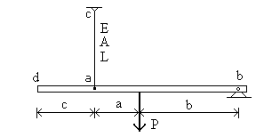 3. In the
figure, bar bd is rigid, and cable ac has the properties shown.
3. In the
figure, bar bd is rigid, and cable ac has the properties shown.
a) Name the equilibrium equation that yields the force in cable ac.
Moment equilibrium about point b.
b) Name the type of motion that bar bd can have.
Rotation about point b.
c) How does knowledge of the force in cable ac allow to determine the displacement at a?
From the force F in cable ac, get the cable elongation FL/EA, which is also the displacement at point a.
d) How does knowledge of the displacement of point a allow to determine the displacement of any other point of the bar?
The displacement v at a point at distance r from point b is vertical and equal to rq, where q is the bar rotation. So for any pair of points,
v1/v2 = r1/r2.
e) Describe the sequence of operations by which to determine the displacement at d caused by a given load P.
1) Determine the force in the cable by the equation in a).
2) Determine the displacement at point a as in c).
3) Determine vd from va as in d).
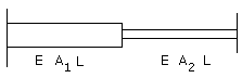
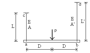 4. In the
figure, bar ab is rigid, and cables ac and bd have the properties shown. How
should the cable flexibilities be related if
4. In the
figure, bar ab is rigid, and cables ac and bd have the properties shown. How
should the cable flexibilities be related if
a) bar ab is to remain level?
By statics, the forces in the cables are equal. The bar remains level if the cable elongations are equal. This require equal flexibilities: L/EA = L'/E'A'.
b) bar ab is to tilt clockwise?
L'/E'A' > L/EA
c) bar ab is to remain remain level, and P is applied at the quarter point from a?
By statics, the force in cable ac is 3 times the force in cable bd. For the cable elongations to be equal, the flexibility of ac needs to be 1/3 that of cable bd: L/EA = (1/3)L'/E'A'.
Statically Indeterminate Problems
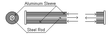
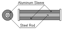 5.
The steel rod and aluminum sleeve assembly may be modeled as two springs in
parallel whose axial stiffness k is the sum of the constituent stiffnesses kst
and kal. Assuming that the cross sectional areas and the moduli
of elasticity are related as follows,
5.
The steel rod and aluminum sleeve assembly may be modeled as two springs in
parallel whose axial stiffness k is the sum of the constituent stiffnesses kst
and kal. Assuming that the cross sectional areas and the moduli
of elasticity are related as follows,
Ast = 1.5Aal
Est = 3Eal
a) What is the ratio of each spring stiffness to the stiffness of the assembly ?
kst = EstAst/L, kal = EalAal/L, k = EstAst/L + EalAal/L
kst/k = EstAst/(EstAst + EalAal) = 4.5/(4.5 + 1) = 0.818
kal/k = EalAal/(EstAst + EalAal) = 1/(4.5 + 1) = 0.182
b) If an axial load P = 10 k. is applied at the ends, what will be the axial forces in the steel tube and the aluminum sleeve?
Nst = (kst/k)P = 8.18 k
Nal = (kal/k)P =1.82 k
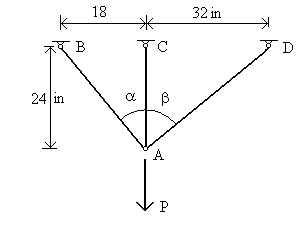 6.
For the three-bar truss,
6.
For the three-bar truss,
a) Write the equilibrium equations governing the forces in the three bars.
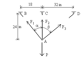
F1sina - F3sinb = 0.6F1 - 0.8F3 = 0
F1cosa + F2 + F3cosb = 0.8F1 + F2 + 0.6F3 = P
b) Write the deformation-displacement relations expressing the bar elongations in terms of the displacements (u, v) of joint A.
d1 = usina - vcosa = 0.6u - 0.8v
d2 = -v
d3 = -usinb - v cosb = - 0.8u - 0.6v
c) Write the force deformation relations, assuming the bars have the same EA.
d1 = 30F1/EA
d2 = 24F2/EA
d3 = 40F3/EA
d) The equations written above should form a system of as many equations as unknowns.
How does the force method proceed?
1) Obtain the compatibility equation by Gauss-elimination of u and v from the three equations in (b)
2) Express the compatibility equation in terms of the forces by means of equations (c).
3) Solve the system of 3 equations: two equations in (a) and one compatibility equations for the three unknown forces.
4) Compute the deformations using the equations (c)
5) Determine the displacements by solving two of the equations (b).
How does the displacement method proceed?
1) Rewrite the equations in (c) as stiffness equations: forces in terms of elongations.
2) Substitute for the elongations their expressions in (b).
3) Substitute for the forces in the equilibrium equations (a).
4) Solve the two equations thus obtained for the two displacements.
5) Obtain the forces from their expressions in step 2).
Thermal Stresses
7. The two bar system is maintained between two rigid walls. If the temperature of the left bar is increased,
 a) Will the
left bar be in tension or compression? Will its length increase or
decrease?
a) Will the
left bar be in tension or compression? Will its length increase or
decrease?
The left bar is restrained from elongating, so it will be
in compression.
Its length will increase by less than the free thermal deformation.
b) Answer the same questions for the right bar.
By statics, the right bar has the same compression force as the left bar.
Its length will decrease since it is in compression and it has no thermal strain. This decrease in length must be equal to the increase in length of the other bar, since the walls maintain a constant total length.
c) If the temperature of both bars is increased by the same amount, and assuming A1 > A2, will the joint of the two bars move to the left or to the right?
If the bars are cut at their joint, they would elongate each by the free thermal deformation dT = aLDT. That would create an overlap of 2dT at the joint. To maintain geometric continuity, equal compressive forces are developed n the bars. The elastic shortening these forces cause is smaller in the stiffer bar, which is the bar on the left. Thus the net joint displacement is to the right.
Here's another way of saying this: Each bar wants to push the joint outward. Bar 1 is the bully, and wins out.
8.
The sleeve-rod assembly is maintained between two rigid plates. If the
temperature of the system is increased by a uniform amount, and given that the
coefficient of thermal expansion of aluminum is larger than that of steel, will
the aluminum sleeve be in tension or in compression? What will be the state of
the steel rod?
 By statics, the total
force on a cross section must be zero. By geometry, the length of the sleeve and
of the rod must remain the same. The aluminum would like to expand more
than the steel, which has to restrain it. Thus the aluminum sleeve will be
in compression, and the steel rod will have an equal tension.
By statics, the total
force on a cross section must be zero. By geometry, the length of the sleeve and
of the rod must remain the same. The aluminum would like to expand more
than the steel, which has to restrain it. Thus the aluminum sleeve will be
in compression, and the steel rod will have an equal tension.