 |
 |
Figure 1. |
Figure 2. |
Operations Manual
Pilat (University of Washington)
Mark 3 and Mark 5
Source Test Cascade Impactor
by
Dr. Michael J. Pilat
email: mpilat@u.washington.edu
Department of Civil Engineering
University of Washington
Seattle, WA 98195 USA
January 1998
Table of Contents
Page
Table of Contents |
2 |
List of Figures |
3 |
List of Tables |
3 |
| I. | Instructions for Pilat (UW) Mark 3 and Mark 5 Cascade Impactors | 4 | |
| A. | Function of Pilat (UW) Source Test Cascade Impactor | 4 | |
| B. | Description of Pilat (UW) Cascade Impactor Components | 4 | |
| C. | Aerodynamic Cut Diameters (da50s) for Pilat Mark 3 Impactor | 7 | |
| D. | Aerodynamic Cut Diameters (da50s) for Pilat Mark 5 Impactor | 12 | |
| E. | Gas Pressure Drop for Mark 5 | 20 | |
| F. | Operating Procedures for Pilat Mark 3 and 5 Cascade Impactors | 21 | |
| G. | Example Particle Size Measurement Source Test | 23 | |
| II. | Impactor Loading Procedure for Pilat (UW) Mark 3 & 5 Cascade impactors | 32 | |
| III. | Impactor Unloading Procedure for Pilat (UW) Mark 3 & 5 Cascade Impactors | 34 | |
| IV. | Reference Literature | ||
| A. | "Source Test Cascade Impactor" by M. J. Pilat, D. S. Ensor, and J. C. Bosch. Atmospheric Environment, 4 671-679, (1970). | ||
| B. | "Size Distribution of Particulates Emitted from a Horizontal Spike Soderberg Aluminum Reduction Cell." by T. R. Hanna and M. J. Pilat. Air Poll. Control Assoc. Journal, 22 533-536. (1970). | ||
| C. | "Size Distribution of Aerosols from a Kraft Recovery Furnace." by J. C. Bosch, M. J. Pilat, and B. F. Hrutfiord. Technical Association of Pulp & Paper Journal, 54 1871-1875. (1971). | ||
| D. | "Relationship of Plume Opacity to the Properties of Particulates Emitted from Kraft Recovery Furnaces." by S. Larssen, D. S. Ensor, and M. J. Pilat. Technical Association of Pulp & Paper Journal, 55. 88-92. (1972). | ||
| E. | "Size Distribution of Particulate Emissions from a Pressurized Fluidized Bed Coal Combustion Facility." by M. J. Pilat and T. W. Steig. Atmospheric Environment, 17 .2429-2433. (1983). | ||
| F. | "Airborne Particulate Emissions from a Chromic Acid Anodizing Process Tank" by R. C. Pegnam and M. J. Pilat, J. of Air & Waste Management Assoc. 42 303 - 308 (March 1992). |
List of Figures
Fig. No. Page
1. Cross Section of Pilat (UW) Mark 3 Cascade Impactor 5
2 Cross Section of Pilat (UW) Mark 5 Cascade Impactor 6
3. Expanded View of Parts of Pilat (UW) Mark 3 Cascade Impactor 7
4. Calculated Aerodynamic Cut Diameters (d50s) for Pilat (UW)
Mark 3
Source Test Cascade Impactor (Temp. of 100, 300, & 500oF) 9
5. Calculated Aerodynamic Cut Diameters (d50s) for Pilat (UW)
Mark 3
Source Test Cascade Impactor (Temp. of 500, 1000, & 1500oF)
10
6 Mark 5 Jet Stage Arrangement for 0.1 to 0.3 acfm Flow 13
7 Mark 5 Jet Stage Arrangement for 0.3 to 0.5 acfm Flow 14
8 Mark 5 Jet Stage Arrangement for 0.5 to 0.8 acfm Flow 15
9 Mark 5 Jet Stage Arrangement for 0.8 to 1.0 acfm Flow 16
10 Calculated d50s for Pilat Mark 5 Cascade Impactor (0.1 to 0.3
acfm) 18
11 Calculated d50s for Pilat Mark 5 Cascade Impactor (0.3 to 0.5
acfm) 19
12 Calculated d50s for Pilat Mark 5 Cascade Impactor (0.5 to 0.8
acfm) 20
13 Air Pressure Drop versus Air Flow Rate for Mark 5 Impactor 21
14. UW Mark 3 Cascade Impactor Sampling Train 23
15. Data Sheet for Pilat (UW) Cascade Impactor Test 32
16. Example Size Distribution Graph 33
List of Tables
Table No.
1 Jet Dimensions of Pilat Mark 3 Source Test Cascade Impactor 4
2 Jet Dimensions of Pilat Mark 5 Source Test Cascade Impactor 5
3 Size Data for Example Source Test 30
I. Instructions for Pilat (UW) Mark 3 and Mark 5 Cascade
Impactors
A. Function of Pilat (UW) Source Test Cascade Impactor
The eleven jet stage Pilat (University of Washington) Mark 5
Source Test Cascade Impactor is essentially an elongated version
of the seven jet stage Mark 3 Pilat (University of Washington)
Source Test Cascade Impactor. The seven jet stage Pilat (Univ. of
Washington) Mark 3 Source Test Cascade Impactor was developed at
the University of Washington Department of Civil Engineering for
measuring the size distributions (0.3 to 20 micron diameter size
range) of particles in stacks and ducts at air pollutant emission
sources. This instack cascade impactor was developed because at
that time (1968), there were no available instack cascade
impactors. This instack cascade impactor was needed by Professor
Pilat and his graduate students for their research projects
regarding the design and evaluation of particulate air pollutant
control equipment and the characterization of the size
distribution and chemical composition of particles emitted from
industrial plants. The University of Washington (Pilat) cascade
impactor is inserted inside the duct or stack to minimize
sampling tubing wall losses and water condensation problems. The
11 stage Mark 5 model was developed a few years later to provide
more jet stages and was initially used for measurements upstream
of particle control equipment (at the higher particle
concentrations). The parts of the Mark 3 and Mark 5 models are
interchangeable. Size distributions of aerosol particles at air
pollutant emission sources are needed to:
1. Design new air pollutant removal equipment;
2. Measure the particle collection efficiency as a function of
particle size of existing particulate control systems; and,
3. Characterize the aerosol emissions from the various sources.
B. Description of Pilat (UW) Cascade Impactor Components
The Pilat Mark 3 and Mark 5 cascade impactors consist of a
threaded cylindrical casing, impaction jet stages, particle
collection plates, threaded inlet and outlet sections, and a
filter holder in the outlet section (for a 47 mm diameter final
filter). Fig. 1 shows a cross-section of the Mark 3 and Fig. 2
shows the Mark 5, and Fig. 3 illustrates the individual parts.
The number of jets in each jet stage and the number of jets per
stage are shown for the 7 stage Mark 3 model in Table 1 and the
11 stage Mark 5 in Table 2. Note that the Mark 3 and Mark 5 jet
stages 1, 2, 3, 4, and 5 are identical in both impactors. The
Mark 3 jet stage number 6 and the Mark 5 jet stage number 7 have
the same jet diameters and number of jets.
|
|
Figure 1. |
Figure 2. |
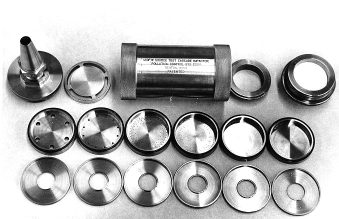 |
Figure 3a. |
 |
Figure 3b. |
Table 1
Jet Dimensions of Pilat (UW) Mark 3 Source Test Cascade
Impactor
| Jet Stage |
No. of Jets |
Jet Diameter (inches) |
Jet Depth (inches) |
Jet-to-Plate Clearance (inches) |
Jet Depth Jet Diameter |
Jet-to-Plate Jet Diameter |
| 1 | 1 | 0.5000 | 1.500 | 0.560 | 2.09 | 0.78 |
| 2 | 6 | 0.2280 | 0.125 | 0.255 | 1.60 | 1.80 |
| 3 | 12 | 0.0960 | 0.125 | 0.125 | 1.97 | 1.97 |
| 4 | 90 | 0.0310 | 0.125 | 0.125 | 4.03 | 4.03 |
| 5 | 110 | 0.0200 | 0.063 | 0.125 | 3.15 | 6.25 |
| 6 | 110 | 0.0135 | 0.030 | 0.125 | 2.22 | 9.26 |
| 7 | 90 | 0.0102 | 0.030 | 0.125 | 3.00 | 12.50 |
The number of jets and jet dimensions for the Mark 5 model are shown below in Table 2. Note that only 11 or less jet stages can be used in the Mark 5 during sampling. However, there are the extra jet stages furnished to enable the Mark 5 model to be arranged in at least three different sampling configurations (ranging from the higher gas volumetric flow rate to lower gas volumetric flow rates).
Table 2
Jet Dimensions of Pilat (UW) Mark 5 Source Test Cascade
Impactor
| Jet Stage |
No. of Jets |
Jet Diameter (inches) |
Jet Depth (inches) |
| 1 | 1 | 0.5000 | 1.500 |
| 2 | 6 | 0.2280 | 0.125 |
| 3 | 12 | 0.0960 | 0.125 |
| 4 | 90 | 0.0310 | 0.125 |
| 5 | 110 | 0.0200 | 0.063 |
| 6 | 110 | 0.0157 | 0.030 |
| 7 | 110 | 0.0135 | 0.030 |
| 8 | 105 | 0.0118 | 0.030 |
| 9 | 105 | 0.0102 | 0.030 |
| 10 | 78 | 0.0102 | 0.030 |
| 11 | 58 | 0.0102 | 0.030 |
| 12 | 40 | 0.0102 | 0.030 |
| 13 | 36 | 0.0102 | 0.030 |
The collection plates for Mark 3 stages 2 through 7 (Mk 5 stages 2 - 11) are donut shaped, allowing for particle impaction upon the annular shaped collection plate and for the sampled gas or air to flow through the center or the "donut hole" and on to the next jet stage. The final particle collection "stage" is a filter holder designed for glass fiber filters (although other filter materials such as Teflon can be used, but care needs to be taken because some other filter materials such as Teflon have much a greater gas pressure drop compared to glass fiber filters). This filter holder is incorporated into the outlet section of the cascade impactor using a collar to hold the filter in place. The filter collar has a hole in it so that the dowel pin in the outlet section will fit into the filter collar hole, preventing it from rotating when the outlet section is tightened (screwed onto) the cylindrical casing. The rotation of the filter collar could cut the filter. The use of a Teflon gasket between the filter collar and the filter and between the filter and the mesh screen is helpful to protect the filter from being cut or damaged from the pressure (also the Teflon gasket helps to prevent the filter fibers from sticking to the mesh screen, especially if some acid condensation occurs). The filter paper is supported by a fine mesh screen and below the fine mesh screen is a perforated support plate. A cross sectional view with an air flow diagram of the Mark 3 Cascade Impactor is illustrated in Fig. 1 and Fig. 2 shows the Mark 5. Fig. 3 shows the parts of a disassembled impactor.
There are a number of different inlet diameters of the sampling nozzles for the impaction inlet section. The nozzle outlet bores are all 0.500 inches diameter which acts as the #1 jet stage (the nozzle opening tapers out to a jet of 0.500 inches diameter). One 3/32 inch by 2-1/8 inch inside diameter O-ring is used on each jet stage and on the filter collar (for a total of seven on the Mark 3 and 11 on the Mark 5). One 1/16 inch by 2-5/8 inch inside diameter O-ring is used on the outlet section. Viton O-rings are recommended for temperatures of 250 - 500F; for temperatures exceeding 500F, eliminate the O-rings and use an extra collection plate as a spacer after jet stage seven. These O-rings are not absolutely needed for operation of the Mark 3 and Mark 5 cascade impactors because of the smooth finish on the 316 stainless steel parts. However, it is a good idea to use them as it helps the jet stages and the particle collection plates to seat or fit nicely.
C. Aerodynamic Cut Diameters (da50s) for Pilat
(UW) Mark 3 Cascade Impactor
The cut diameter is the particle diameter collected with 50%
collection efficiency by that jet stage. The aerodynamic diameter
is the diameter of a spherical particle of unit density (i.e.
density of 1.00 grams/cubic centimeter) which behaves
aerodynamically just the same as the real particle. It has been
conventional for many years to use the cascade impactor jet stage
cut diameters and aerodynamic diameters with cascade impactor
particle size measurements. More recently, the EPA PM10 criteria
air pollutant for particulate matter under 10 microns diameter
refers to the aerodynamic cut diameter of 10 microns. And there
is the EPA (proposed Nov. 1996; promulgated July 1997) PM2.5 with
the aerodynamic cut diameter of 2.5 microns.
The equation for the cascade impactor jet stage aerodynamic cut diameter da50 is given by the equation:
where m is the gas viscosity, Dj is the diameter of the jet holes in that cascade impactor stage, Y50 is the inertial impaction parameter at the 50% particle collection efficiency of that impactor jet stage (Y50 is about 0.145 for cylindrical round jet stages and Y50 does vary a little with the Reynolds number and other variables), C is the Cunningham slip correction factor for the particle of diameter da50, and Vj is the gas velocity at the inlet (upstream inlet to the jet hole) to the gas jet through the impactor jet stage.
The calculated aerodynamic cut diameters or da50s for the Pilat (UW) Mark 3 Cascade Impactor are shown in Fig. 4 for temperatures of 100, 300, and 500oF and in Fig. 5 for temperatures of 500, 1000, and 1500oF. The horizontal axis shows the gas volumetric flow rate through the cascade impactor at stack conditions (actual ft3 gas/minute at the instack cascade impactor conditions). The vertical axis of Fig. 4 and Fig. 5 show the aerodynamic cut diameters for the various jet stages. These Mark 3 Cascade Impactor have been calibrated by experimental measurements performed under EPA funding contracts to Southern Research Institute. Also research funded by EPA concerning the sampling for electrostatically charged particles (such as downstream of elect. precipitators) resulted in experimental calibrations of the Pilat (UW) Mark 3 Cascade Impactor.
Fig. 4 Calculated Aerodynamic Cut Diameters (da50s) for Pilat (UW) Mark 3 Source Test Cascade Impactor (Temp. of 100, 300, & 500oF)
Fig. 5 Calculated Aerodynamic Cut Diameters (da50s) for Pilat (UW) Mark 3 Source Test Cascade Impactor (Temp. of 500, 1000, & 1500oF)
D. Aerodynamic Cut Diameters (da50s) for Pilat (UW) Mark 5
Cascade Impactor
The Mark 5 model is primarily designed for operation with larger
particle mass concentrations where it is necessary to sample at
lower gas flow rates (0.1 to 0.3 acfm). Thus, the Mark 5 is
typically used at the inlet to particulate control devices where
the particle mass concentration is higher (see Figures 6, 7, 8,
and 9 for arrangement of jet stages at the various gas sampling
flow rates). Note that the Mark 5 can be operated at higher gas
flow rates by removing the lower jet stages (i.e. Fig. 9 shows
the 11 jet stage arrangement for the highest gas sampling flow
rates).
The Mark 5 jet stages should not be operated at gas flow rates such that the stage da50 goes below 0.2 microns. Referring to the Figure 12 graph of da versus the gas flow rate, it can be seen that when Stage 11 with 36 jets of 0.0102 inches in diameter goes above approximately 0.65 acfm, the d goes below 0.2 micron diameter. Thus, this jet stage should be removed at flow rates greater than approximately 0.3 acfm and the stage with 12 jet holes of 0.0960 inches in diameter inserted after the inlet jet stage No. 1. (see Figure 7 for the arrangement of jet stages; see Figure 11 for the graph of d50 versus gas flow rate.). With a gas flow rate greater than 0.5 acfm, the stage with 40 jets of 0.0102 inches in diameter should be removed and the jet stage with 6 jets of 0.2280 inches in diameter inserted between the No. 1 inlet jet stage and the stage with 12 jets of 0.0960 inches in diameter. (See Figure 8 for arrangement of jet stages.). At gas flow rates greater than 0.8 acfm, the stage with 56 jets of 0.0102 inches in diameter should be removed and a spacer inserted to take up the space. This spacer should be placed between the last two collection plates (see attached Figure 9 for arrangement of jet stages).
| Number of Jets per Stage |
Jet Diameter (inches) |
||
| Nozzle Jet Stage | 1 | 1 | 0.5000 |
| Collection Plate | 1 | ||
| Jet Stage | 2 | 90 | 0.0311 |
| Collection Plate | 2 | ||
| Jet Stage | 3 | 110 | 0.0200 |
| Collection Plate | 3 | ||
| Jet Stage | 4 | 110 | 0.0157 |
| Collection Plate | 4 | ||
| Jet Stage | 5 | 110 | 0.0135 |
| Collection Plate | 5 | ||
| Jet Stage | 6 | 105 | 0.0118 |
| Collection Plate | 6 | ||
| Jet Stage | 7 | 105 | 0.0102 |
| Collection Plate | 7 | ||
| Jet Stage | 8 | 78 | 0.0102 |
| Collection Plate | 8 | ||
| Jet Stage | 9 | 56 | 0.0102 |
| Collection Plate | 9 | ||
| Jet Stage | 10 | 40 | 0.0102 |
| Collection Plate | 10 | ||
| Jet Stage | 11 | 36 | 0.0102 |
| Collection Plate | 11 | ||
| Outlet Filter |
Fig. 6 Mark 5 Jet Stage Arrangement for 0.1 to 0.3 acfm Flow
| Number of Jets per Stage |
Jet Diameter (inches) |
||
| Nozzle Jet Stage | 1 | 1 | 0.5000 |
| Collection Plate | 1 | ||
| Jet Stage | 2 | 12 | 0.0960 |
| Collection Plate | 2 | ||
| Jet Stage | 3 | 90 | 0.0311 |
| Collection Plate | 3 | ||
| Jet Stage | 4 | 110 | 0.0200 |
| Collection Plate | 4 | ||
| Jet Stage | 5 | 110 | 0.0157 |
| Collection Plate | 5 | ||
| Jet Stage | 6 | 110 | 0.0135 |
| Collection Plate | 6 | ||
| Jet Stage | 7 | 105 | 0.0118 |
| Collection Plate | 7 | ||
| Jet Stage | 8 | 105 | 0.0102 |
| Collection Plate | 8 | ||
| Jet Stage | 9 | 78 | 0.0102 |
| Collection Plate | 9 | ||
| Jet Stage | 10 | 56 | 0.0102 |
| Collection Plate | 10 | ||
| Jet Stage | 11 | 40 | 0.0102 |
| Collection Plate | 11 | ||
| Outlet Filter |
Fig. 7 Mark 5 Jet Stage Arrangement for 0.3 to 0.5 acfm Flow
| Number of Jets per Stage |
Jet Diameter (inches) |
||
| Nozzle Jet Stage | 1 | 1 | 0.5000 |
| Collection Plate | 1 | ||
| Jet Stage | 2 | 6 | 0.2280 |
| Collection Plate | 2 | ||
| Jet Stage | 3 | 12 | 0.0960 |
| Collection Plate | 3 | ||
| Jet Stage | 4 | 90 | 0.0311 |
| Collection Plate | 4 | ||
| Jet Stage | 5 | 110 | 0.0200 |
| Collection Plate | 5 | ||
| Jet Stage | 6 | 110 | 0.0157 |
| Collection Plate | 6 | ||
| Jet Stage | 7 | 110 | 0.0135 |
| Collection Plate | 7 | ||
| Jet Stage | 8 | 105 | 0.0118 |
| Collection Plate | 8 | ||
| Jet Stage | 9 | 105 | 0.0102 |
| Collection Plate | 9 | ||
| Jet Stage | 10 | 78 | 0.0102 |
| Collection Plate | 10 | ||
| Jet Stage | 11 | 56 | 0.0102 |
| Collection Plate | 11 | ||
| Outlet Filter |
Fig. 8 Mark 5 Jet Stage Arrangement for 0.5 to 0.8 acfm Flow
| Number of Jets per Stage |
Jet Diameter (inches) |
||
| Nozzle Jet Stage | 1 | 1 | 0.5000 |
| Collection Plate | 1 | ||
| Jet Stage | 2 | 6 | 0.2280 |
| Collection Plate | 2 | ||
| Jet Stage | 3 | 12 | 0.0960 |
| Collection Plate | 3 | ||
| Jet Stage | 4 | 90 | 0.0311 |
| Collection Plate | 4 | ||
| Jet Stage | 5 | 110 | 0.0200 |
| Collection Plate | 5 | ||
| Jet Stage | 6 | 110 | 0.0157 |
| Collection Plate | 6 | ||
| Jet Stage | 7 | 110 | 0.0135 |
| Collection Plate | 7 | ||
| Jet Stage | 8 | 105 | 0.0118 |
| Collection Plate | 8 | ||
| Jet Stage | 9 | 105 | 0.0102 |
| Collection Plate | 9 | ||
| Jet Stage | 10 | 78 | 0.0102 |
| Collection Plate | 10 | ||
| Spacer | |||
| Outlet Filter |
Fig. 9 Mark 5 Jet Stage Arrangement for 0.8 to 1.0 acfm Flow
The aerodynamic cut diameters for the Mark 5 Pilat (UW) Cascade Impactor are presented in Figures 10, 11, and 12. These graphs are for different arrangements of the jet stages, corresponding to the different gas sampling flow rates at the impactor temperature and pressure.

Figure 10
Calculated da50s for Pilat Mark 5 Cascade Impactor (0.1 to 0.3
acfm)
Figure 11
Calculated da50s for Pilat Mark 5 Cascade Impactor (0.3 to 0.5
acfm )
Figure 12
Calculated da50s for Pilat Mark 5 Cascade Impactor (0.5 to 0.8
acfm )
E. Gas pressure drop for Mark 5
Figure 13 presents the gas pressure drop across one configuration of the Mark 5. The right hand curve is for an arrangement with Teflon gaskets between the stage and the collection plate. Note that it is recommended that this configuration with jet stage No. 11 with 36 holes of 0.010 inches not be operated above 0.3 acfm. It is possible to use the Pilat (UW) Mark 5 Cascade Impactor as a "low pressure cascade impactor" but please note that care must be taken because there can be some leakage of gas around the edges of the cascade impactor jet stage (rather than the gas flowing through the jet holes). The majority of the gas pressure drop is across the last jet stage in the Mark 5 (the number 11 jet stage) and therefore, the use of a gasket between this jet stage and the collection plate may be needed. When operated as a "low pressure cascade impactor" it is necessary to measure the absolute gas pressure downstream of the last cascade impactor jet stage and upstream of the final outlet filter. Because the filter holder is included in the Mark 5 cascade impactor outlet section, for low pressure operation it is necessary to omit the filter in the outlet section so that the gas pressure can be measured at the impactor outlet and then a separate filter holder connected downstream of the gas pressure measurement connection. Although we do not recommend using the Pilat (UW) Mark 5 Cascade Impactor in the low pressure cascade impactor mode, it has been done successfully. The jet stage aerodynamic cut diameters (da50s) for the low pressure operation will need to be calculated using equation 1 and the appropriate Cunningham Correction factor used in this calculation.
Fig. 13 Air Pressure Drop versus Air Flow Rate for Mark 5 Impactor
F. Operating Procedure for Pilat (U of W) Mark 3 and Mark 5 Cascade Impactors
1. Pretest Preparations of Cascade Impactor
2. Necessary Source Test Equipment
A schematic diagram of the source test sampling train is presented in Fig. 14. This train is similar to the EPA Method 5 or EPA Mth 17 particulate sampling train The schematic diagram shows the basic parts of the sampling train, but does not show the instack pitot tube (for isokinetic monitoring of the stack gas velocity) or the pressure and temperature gages in the sampling train.
Fig. 14 UW Mark 3 Cascade Impactor Sampling Train
The list of supplies and apparatus shown below is presented to assist one in identifying the items which might be needed for your operation of the Pilat (U. of W) Mark 3 and Mark 5 Cascade Impactors.
3. Source Test for Particle Size Distribution Measurement
Select the sampling nozzle diameter and
calculate the gas sampling rate or the dry gas meter rate
(Rm) for isokinetic sampling.

8.Impactor disassembly and storage of sample for transportation to laboratory.
a. Drain any condensed moisture from the connecting hoses into the impingers. Save the impinger water to:
1. Calculate the quantity of water vapor in the stack by weighing the impingers.
2. Evaporate the water to measure any condensable material or particles small enough to go through the filter (i.e. the "back-half particulate catch").
b. If the collection plates or inserts need to be changed in the field for more tests, disassemble the impactor in a clean location with no wind. Place the collection plates or inserts and filter into the petri dishes to be re weighed. Take care not to contaminate the collection plates or inserts. The use of forceps or tweezers may be helpful.
c. Note which set of collection plates or inserts is used for each test.
4. Sample Analysis
5. Analyses of Data
G Example Particle Size Measurement Source Test
1. Calculate gas velocity at sampling location
Start by calculating the gas velocity at the location you intend to place the Source Test Cascade Impactor. The data sheet for this example is shown in Fig. 15. Only one gas velocity pitot tube and gas temperature measurement is shown on this data sheet. This example data was taken from a source test on the gases exhausting from a pulp mill Kraft liquor recovery boiler exhaust gas stack test (the 30% water vapor concentration is typical of this source). The gas velocity data measured in this example is a gas temperature T of 290 F (750 R) and a pitot tube pressure differential H of 0.11 inches water with the type S pitot tube. Calculate the gas velocity with a pitot tube calibration factor Kp of 0.83.
2. Calculate the Dry Gas Meter Flow Rate
Calculate the dry gas meter flow rate for isokinetic sampling. Select a nozzle diameter which will give a dry gas meter rate between 0.25 and 0.75 cubic feet per minute. For this example a nozzle diameter of 3/8 inch is selected. The following date is measured at the source test site:

Calculating the gas volumetric flow rate at the dry gas meter, Rm ,

Record the test conditions on the data sheet. Run the source test. The example test started with a dry gas meter reading of 106.34 cubic feet at Time = 0 and ended with a meter reading of 118.95 cubic feet at Time = 20 minutes.
Fig. 15 Data Sheet for Pilat (UW) Cascade Impactor Test
After weighing the collection plate substrates plus particles, the initial weight is subtracted from the final weight for each plate. Divide the change in weight (the weight of particles collected on a certain plate) by the total weight of particles collected on each plate, as shown in Table 3 page . To obtain the cumulative percentages, add the incremental percentages from the filter end.
To obtain the ds From Fig. 4 or 5, the cascade impactor gas sampling flow rate at stack conditions Rs and instack gas temperature Ts are needed. The cascade impactor sampling gas flow rate at stack conditions is calculated from the volume of gas recorded by the dry gas meter and from the volume of water condensed (to account for the water vapor in the sampled gas) corrected to the stack gas temperature and pressure, as follows:
1. Calculation of water vapor volume at dry gas meter conditions
2. Calculation of total volume of gas sampled
3. Cascade Impactor Sampling Gas Flow at Stack Conditions
A comparison of the cascade impactor actual gas-sampling flow rate with the isokinetic sampling rate can be done by dividing the flow Rs by the nozzle cross-sectional area.

Therefore, the actual sampling rate was 6% below the isokinetic rate of 22 ft/sec.
Using the cascade impactor sampling gas flow rate at stack conditions (0.956 acfm) and the stack gas temperature of 290 F (about 300 F) the d's can be obtained from Fig. 4 (page 8) and are listed in Table 3 in the right hand column.
TABLE 3 Size Data for Example Source Test
Plate Number |
Delta Weight (grams) |
Percent Weight |
Cumulative Percent Weight Less than d50 |
d50 (microns) |
1 |
0.01742 |
20.0 |
80.0 |
13.00 |
2 |
0.00734 |
8.5 |
78.0 |
10.00 |
3 |
0.00821 |
9.5 |
68.5 |
3.80 |
4 |
0.00967 |
11.0 |
57.5 |
1.80 |
5 |
0.01245 |
14.0 |
43.5 |
0.51 |
6 |
0.01506 |
17.5 |
26.0 |
0.24 |
7 |
0.01328 |
15.0 |
11.0 |
|
Filter |
0.00937 |
11.0 |
||
Total |
0.08709 |
100.0 |
Plot the cumulative % of particle weight less than the particle d50 size distribution on a log-probability graph (logarithm of particle diameter versus the percent by weight of particles less than a given diameter), such as is shown in Fig. 16. The mass median particle diameter is the particle diameter at which 50% by weight of the particles are smaller.
Fig. 16 Example Size Distribution Graph
Assuming a log-normal particle size distribution, the particle size geometric standard deviation sg is given by:
For this example the particle mass median diameter is about 1.30 microns and the geometric standard deviation can be calculated by:
Of course these two geometric standard deviations (one calculated by the 84.13% diameter / the 50% diameter and the other calculated with the 50% diameter / the 15.87% diameter)are different because the particle size distribution is not a straight line (not really log-normal). One approach to obtain a more representative standard deviation is to calculate it as follows:
In general, it is better to present the particle size information in graphical form rather than merely reporting the mass mean diameter and size geometric standard deviation.
II. Impactor Loading Procedure for the Pilat (UW) Mark 3 and 5 Cascade Impactors
A. Outlet Section of the Pilat (U. of W.) Mark 3 or 5 Cascade Impactor
B. Impactor Substrates
C. Inlet Section of the Pilat (U. of W.) Mark 3 Cascade Impactor
D. Precollector (Either PCSC Precollector or the Right Angle Sampling Attachment)
E. Leak Check
F. Wrapping
III. Impactor Unloading Procedure for Pilat (UW) Mark 3 and 5 Cascade Impactors
A. Preliminary
B. Sampling Nozzle and Impactor Inlet Section (or Precollector)
C. Impactor Substrates
D. Outlet Section
E. Reloading Preparation
IV. Reference Literature
A. "Source Test Cascade Impactor" by M. J. Pilat, D. S. Ensor, and J. C. Bosch. Atmospheric Environment, 4 671-679, (1970).
B. "Size Distribution of Particulates Emitted from a Horizontal Spike Soderberg Aluminum Reduction Cell." by T. R. Hanna and M. J. Pilat. Air Poll. Control Assoc. Journal, 22 533- 536. (1970).
C. "Size Distribution of Aerosols from a Kraft Recovery Furnace." by J. C. Bosch, M. J. Pilat, and B. F. Hrutfiord. Technical Association of Pulp & Paper Journal, 54 1871-1875. (1971).
D. "Relationship of Plume Opacity to the Properties of Particulates Emitted from Kraft Recovery Furnaces." by S. Larssen, D. S. Ensor, and M. J. Pilat. Technical Association of Pulp & Paper Journal, 55. 88-92. (1972).
E. "Size Distribution of Particulate Emissions from a Pressurized Fluidized Bed Coal Combustion Facility." by M. J. Pilat and T. W. Steig. Atmospheric Environment, 17 .2429-2433. (1983).
F. "Airborne Particulate Emissions from a Chromic Acid Anodizing Process Tank" by R. C. Pegnam and M. J. Pilat, J. of Air & Waste Management Assoc. 42 303 - 308 (March 1992).
HTML Revision 2/24/1999