| TCSS 371A - Fall 2005 Project 2 - Analog Oscilloscope and Serial Port Project Report Due November 23 (Updated 11/20/05) |
|---|
In the early 1960s, a standards committee, known as the Electronic Industries Association (EIA), developed a common serial bus interface standard for asynchronous data communications equipment, named RS232. It is still used today for connecting peripheral equipment, like printers, to computers, as well as connecting computers together. It is now being replaced by a faster asynchronous serial bus, USB or Universal Serial Bus. Originally, data communications was thought to mean digital data exchange between a centrally located mainframe computer and a remote computer terminal, or possibly between two terminals without a computer involved. These devices were linked by telephone voice lines, and consequently required a modem at each end for signal translation. While simple in concept, the many opportunities for data error that occur when transmitting data through an analog channel require a relatively complex design. It was thought that a standard was needed first to ensure reliable communication, and second to enable the interconnection of equipment produced by different manufacturers, thereby fostering the benefits of mass production and competition. It specified signal voltages, signal timing, signal function, a protocol for information exchange, and mechanical connectors. You will see both 25 pin and 9 pin connectors used for RS232 today.
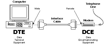
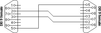
If the full EIA232 standard is implemented as defined, the equipment at the far end (left end below) of the
connection is named the DTE device (Data Terminal Equipment, usually a computer or terminal),
and has a male connector. Equipment at the near end (right end below) of the connection (the telephone line interface)
is named the DCE device (Data Circuit-terminating Equipment or Data Communications Equipment,
usually a modem), has a female connector, and utilizes the same available pins for signals and
ground. The cable linking DTE and DCE devices is a parallel straight-through cable with no
cross-overs or self-connects in the connector hoods. If all devices exactly followed this
standard, all cables would be identical, and there would be no chance that an incorrectly
wired cable could be used. This drawing shows the orientation and connector types for DTE and
DCE devices:
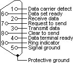
The signals on an RS232 9 pin connector are:
If one wants to connect two computers together, a "null modem" connection can be used in place of the pair of modems. Since both computers are DTE's, the straight through connection from a DTE to a DCE will not work. A null modem crosses the send and receive lines and connects the other wires, the flow control or "handshaking signals", correctly for a DTE to communicate with another DTE.
The configuration for a null modem is: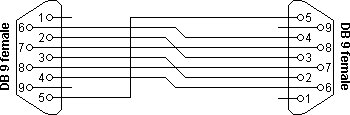
"Full Handshaking Null Modem"
Sometimes null modems are connected with "loop back" connections to "fake" the handshaking as follows:
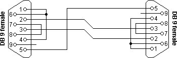
"Loop back Handshaking Null Modem"
Sometimes designers actually don't bother with the handshaking signals at all. They don't program the equipment to either look at or to generate the signals:
"No Handshaking Null Modem"
This lack of standard for a connection often gives one fits when configuring a system! Maybe you have been there? For our project we will ignor handshaking. That will make it simplier for us, but still not at all trivial.
RS232 transmits a sequence of bytes, each of which is transmitted as a sequence of pulses. These pulses are sent at a selected Baud (or bit) rate:
     Baud rate: Max speed of transmission of bits:
         Typically 110, 300, 1200, 2400, 4800, 9600, 19200 bits/sec
The protocol for the sequence of pulses representing the bytes of ASCII Characters is:
     Start bit:
         A first bit always of the same polarity for equipment to sync on

     Data Bits:
         The useful data follows the start bit:
         Typically 5, 6, 7, or 8 bits

     Parity Bit:
         A bit used for error checking:
         Even Parity, Odd Parity, Mark Parity, Space Parity, No Parity

     Stop Bits:
         The trailing bits after the data and parity to ensure time to "catch" data between bytes:
         Typically 1, 1.5, or 2 bits
Understand that both commmunicating devices must be using the same protocol parameters for the communication to be successful.
import java.io.*;
import javax.comm.*;
public class SimpleWrite
{
    public static void main(String[] args) throws Exception
    {
        OutputStream outputStream;
        outputStream = get_the_serial_port();
        byte[] data = {'a'};      // string sent
        for (int i = 0; i < 1000; i++)
        {
            outputStream.write(data);
            System.out.println ("i = " + i);
            Thread.sleep(1000);   // milliseconds suspended
        }
    }
    public static OutputStream get_the_serial_port() throws Exception
    {
        CommPortIdentifier portId;
        portId = CommPortIdentifier.getPortIdentifier("COM1");  // COM Port #
        SerialPort serialPort;
        serialPort = (SerialPort) portId.open("SimpleWriteApp", 2000);
        serialPort.setSerialPortParams(9600,   // baud rate
                SerialPort.DATABITS_8,
                SerialPort.STOPBITS_1,
                SerialPort.PARITY_NONE);
        return serialPort.getOutputStream();
    }
}
This program uses the javax.comm package. It is not included in the java JDK (jre). It can be obtained at:
http://java.sun.com/products/javacomm/index.jsp
For this project, we want to observe the serial stream of pulses that can be sent over the serial cable, and UNDERSTAND how they are transmitted. We will work in groups of 2. Keep good records as you do the project. You will have to submit a report on it.
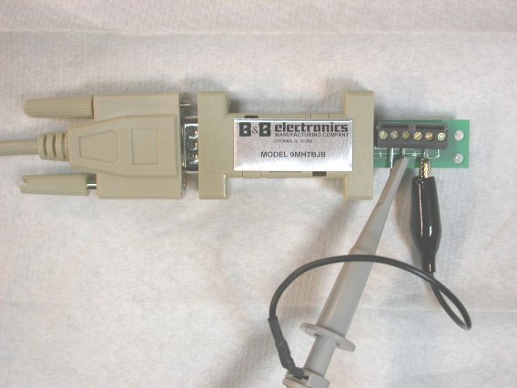
Each individual should submit a write-up.1) Hook channel 1 of the analog oscilloscope to the output of a serial port (Ground is pin 5). The transmitted signal is on pin 3. Here is a picture of our oscilloscope connected to the serial cable from our computer.
Hook channel 2 to the pulse generator output and set the pulse rate to approximately 9600 Hz.
2) Transmit a character using Java Comm Library (javax.comm is installed on the laboratory computer JDK's). Describe what you see. Draw a picture of your wave form identifying the frequency, voltage between the transmitted character, the value of a "1" and a "0" level, the start bit, the data bits and their order and orientation, the partiy bit, and the stop bits. Explain how you know those identifications are correct. How did you use the pulse generator display to confirm your identification of the bit rate?
3) Transmit a zero (the number 0, not the character '0'), and record the result.
4) Choose other characters to transmit, and record the results.
5) Choose alternate values for EACH parameter: Baud rates, data bits, parity, and stop bits. Record the results and observations.
6) Change the sleep time in the program. Record the results and observations. Make the sleep time equal to 0.
7) Have your program increment the byte each iteration. (Suggestion: Start by setting up an iteration to repeat sending just two characters, say an "a" and a "b". Then increase the number of iterations to repeat transmiting "a" through "e". The challenge will be to observe the sequence on the oscilloscope.) Record results and observations.
8) Now output a string of data and record your results and observations (begin with just 2 characters).
9) Explore any other interesting things you might think of.
The report should be neat and professional, making your procedure, recordings, and observations clear. Include in your report feedback on the project: Was it a good learning experience, and what can be done to improve it?