Dualmode Station Design and Commentary as Presented as Figure 3 in U.S. Patent # 6,169,954 (Homer T. McCrary) which Describes a Personalized Transportation System
More details on the PTS can be found by doing a search at the website for the U.S. Patent and Trademarks Office. In addition to this basic patent, three others (6,198,994, 6,249,724 and 6,276,542) have been issued to McCrary of Davenport, CA.
Embarking and Disembarking Stations
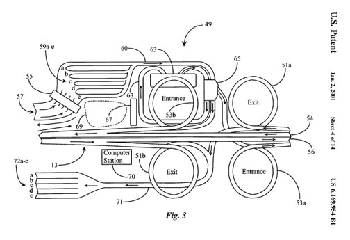
Figure 3 is an exemplary overhead view of an embarking-disembarking station of a Personalized Transportation System (PTS) according to an embodiment of the present invention. This station is exemplary of an embarking/disembarking point for commuters entering and exiting the PTS. The station may vary in architecture and functions as required to facilitate particular areas along the PTS. For example, if the station is in an urban area, architecture and facilities will serve those needs. If the station is in a rural area, then architecture and facilities may be significantly less complex than shown in Figure 3 in accordance to rural needs. It can be assumed that in this particular example, the station is a full-service station. It has a plurality of lanes dedicated to connecting commuters to various facilities, junctions to normal roadways, points of entrance, points of departure, and so on.
The controlled roadway, now defined as a connected plurality of previously-described elevated roadway sections, comprises two main traveling lanes (54 and 56) in this embodiment, one for each direction of travel on the PTS. Commuter travel in this example is bi-directional. In other instances, there may be fewer or more lanes as required to service an area or region. Lane (54) has an exit loop (51a) located at the site of the station which is adapted to allow commuters to exit the PTS and to continue on surface roads and streets to nearby destination locations and so on. The intersection of lane (54) with exit lane (51a) is actually off the figure to the right. Lane (54) also has an entrance loop (53b) located at the station which is adapted to allow commuters to enter the PTS for remote destination points (typically other stations located near their ultimate destinations). Lane (56) has an exit loop (51b) and an entrance loop (53a), which are adapted as described above with loops (51a and 53b).
Commuters wishing to enter the PTS may do so by first entering the station at a convenient staging location such as at entrance (57). Curved entrance arrows proximate to staging location (57) illustrate direction of travel into the station . At this point each commuter is manually operating a Personal Vehicle (PV). In some embodiments a PV diagnostic facility (55) is provided as an enclosed structure with through-lanes having bays adapted to perform various vehicle diagnostic routines and verification routines associated with commuter authorization to travel on the PTS. In this example there are 5 lanes with each lane having one associated bay typically located inside the structure. Each bay is equipped with identical diagnostic and service facilities. Commuters simply drive their PVs into a lane and through an appropriate bay inside the enclosure, and a wireless communication connection is established between the appropriate bay and each PV on-board computer (OBC).
Diagnostic functions performed by a bay (55) may include but are not limited to checking PV batteries for integrity, checking tire pressure and wheel alignment, checking status and integrity of proximity sensors, testing OBC steering and speed control capabilities, testing OBC communication capabilities, and so on. Typically all of these functions and checked and monitored by each OBC for a PV, whether the PV is in a station or not. It is only really necessary that the OBC communicate the latest monitored information to the stations computer system, which is in constant communication with the Master computer system for the PTS.
By checking each vehicle as it comes into a station for access to the PTS, it is assured that no unstable vehicles are allowed to enter PTS . Verification of driver fitness and authorization may be done as well and may include, but is not limited to, verifying driver identification, verifying destination, securing payment for travel, checking driver alertness or medical status, security check for contraband, and so on.
In an alternative preferred embodiment of the present invention it is not necessary to encumber stations with the vehicle checks. Alternatively PVs and their OBCs are in constant wireless communication with the PTS Master computer system, and all PVs that might be eligible for travel on the PTS. In this system each PV is known to the Master computer system by a unique identifier, and each PV is constantly tracked, so all necessary information is known to the Master system. In such a system, as is further described below, commuters may also communicate travel plans to the PTS system ahead of time, make payments and the like, and the Master system considers all PVs at all times, whether the PVS are in the PTS system or not. There are many advantages to this comprehensive system.
In a preferred embodiment of the present invention PVs travel on the controlled roadway under power only from their on-board potential energy sources, without power derived from the roadway. This provides for the least complicated architecture for the roadway itself. In this embodiment PVs are monitored and checked at entrance or at some near time prior to entrance for the energy state of the on-board potential energy source, such as a battery for an EV, against user-provided destination information. Adequate power capability with a safety margin is required for authorization to enter.
Medical checks may be made for commuters as well, such as intoxication tests, blood pressure or heart condition checks, history of phobias, and so on. For example, a driver with a phobia of bridges or heights may be advised not to travel on PTS . A person found to be inebriated might be banned from travel on PTS. High-risk individuals for heart attack or stroke may be advised before traveling and so on. Security checks may include checking for pets, explosives, weapons, or other common contraband. In a preferred embodiment, records are kept on the Master computer for any and all data important to function and safety for the PTS.
In station, after being cleared for entrance, commuters are directed to one of a plurality of staging lanes (59a-e). Staging lanes (59a-e) are adapted to accept individual PVs destined for a same station or general destination location. In this way, a group of PVs comprising multiple PVs destined for a same location may be caused to travel in close proximity to one another such that they may exit together at a next common or destination station. This is preferred as a means for maximizing energy efficiency for travel on PTS. A traveling group of PVs may be construed simply as more than one PV. The number of PVs traveling in any one group will vary according to congestive status of PTS as a whole. For example, at odd hours not associated with regular commuting times, single PVs may be allowed to enter PTS and travel without being associated with a group.
Upon entrance to the station, after maintenance and other checks, manual control of PVs is passed over to computer control from PTS. Now individual OBC's associated with each PV are in constant communication with a local computer control station (70) that interfaces with a Master PTS computer system. According to information transmitted from local computer station (70) and destination parameters associated with each packet of PVs, individual groups of PVs are caused to embark to their destinations in unison maintaining a constant speed and spacing between each PV in the line. For example, local computer station (70) knows the positioning and time of arrival of any through-groups of PVs traveling on lanes (56 or 54). A command for one of lines (59a-e) arrives at such timing when it is known that the line may enter it's designated lane safely.
As a group from lanes (59a-e) is released for entrance, it travels according to the directional arrow shown on lane (60) through a turnstile (65). Turnstile (65) is adapted to direct a group of PVs to an appropriate entrance lane for either lane (56 or 54) as illustrated by directional arrows. For example, if a group is designated for entrance to lane (56), then it enters lane (56) by way of entrance loop (53a) and merges in with passing traffic at the appropriate and constant speed of travel on PTS . Similarly, if a group is designated to travel on lane (54), then turnstile (65) is switched to allow entrance to lane (54) by way of entrance loop (53b).
In one embodiment, one of lanes (59a-e) is designated to accept PVs having problems or having unauthorized PVs or unfit drivers. When such a line reaches turnstile (65), it is directed or switched to an internal access loop (61) that is adapted to direct such vehicles into a maintenance facility (63) wherein problem resolution services may be performed. If successful problem resolution is reached, an approved PV may exit facility (63) on loop (61) and re-enter turnstile (65) where it may be integrated into an appropriate next group of PVs headed for a same destination.
If for some reason a problem cannot be resolved, an additional return lane (not shown) may be provided and adapted to return such PVs back to entrance location (57) where they may undergo additional diagnostics at station (55), or perhaps, be swapped with an approved PV from a fleet of such vehicles that may be kept at station. If a PV cannot be controlled by PTS because of an OBC failure, then it may not be allowed to enter any of lanes (59a-e). In this case, it may be redirected from station (55) to a parking area or to building (63) via alternate lanes (not shown). In a simple alternative, PVs failing one or more entrance requirement receive an electronic report card detailing the reason for rejection, and a recommendation for correction for future attempts at use of a PTS, and are then switched off the system and back onto the surface streets. There are many variable possibilities.
PVs traveling on PTS need not enter station when exiting lanes (54 and 56). A suitable exit lane (71) is provided for all exiting PVs. For example, a line of PVs exiting from lane (54) will use exit loop (51a) and access exit lane (71) at a suitable merge location. PVs exiting lane (56) use exit loop (51b) and merge onto lane (71) at the same merge location. As PVs decelerate and merge onto lane (71), they are directed to one of lanes (72a-e) according to known ultimate destination locations obtained when they entered PTS from another station. Lanes (71a-e) represent passageways to local streets or roadways or freeway access roads leading to appropriate ultimate destinations. While PVs are in lanes (71a-e), manual operation for each PV is restored to the driver allowing the driver to assume control and to continue on to a final destination.
In one embodiment, a suitable parking structure represented by dotted area (69) may be provided with entrance and exit lanes for commuters who work within walking distance of station . Parking structure (69) may be as simple as an open parking lot, or as complex as a multi-story-parking garage. In the latter case, structure (69) may include facilities at each parking stall for re-charging PV batteries, in the case of EVs or hybrid vehicles for a return trip, or refueling for internal-combustion-powered PVs, and other apparatus such as overhead storage monorails for very efficient storage. In this way, commuters may return to a fully ready PV ready for a return commute, and PVs may be readily found as needed.
It will be apparent to one with skill in the art that a variety of lanes, facilities and other support architecture may be utilized in a station such as station without departing from the spirit and scope of the present invention. For example, additional diagnostic and maintenance facilities may be provided for multi-passenger PVs such as PV 17 of FIG. 1. Also, though not shown in FIG. 3, curved acceleration and deceleration ramps may be of fishook design, such that centripetal force effects are maintained at a constant value as vehicles are caused to accelerate and decelerate.
In one embodiment, PVs such as PV 17 may be intermingled with PVs such as PV 15 for traveling in lines with perhaps the multi-passenger PV being the lead vehicle. In still another embodiment, PVs such as PV 15 of FIG. 1 are kept at station, and may be used by passengers who first park their gas powered vehicles in a designated area at a station such as station, and so on. In a preferred embodiment, however, PVs such as PV 15 of FIG. 1 are dual-mode vehicles either owned or leased by individual commuters. The purchase or lease of such vehicles may insure unlimited ridership on PTS while infrequent commuters must use multi-passenger vehicles such as PV 17 of FIG. 1.
Last modified: March 06, 2004