The SC-2 is a significant upgrade from the previous SC-1 (previously known as SimpComp). This computer has been designed to support executive-mode programming for protection of the kernel in real-time (RT) operating systems (RTOS) support for multi-tasking applications. The SC-2 has many features that are found on higher end computers but is designed to tackle lower end real-time control and instrumentation applications. Floating point instructions are supported in this model by C library emulation. Some opcodes have been reserved for future implementation of a floating point hardware support. Most of the target RT applications will not need floating point arithmetic.
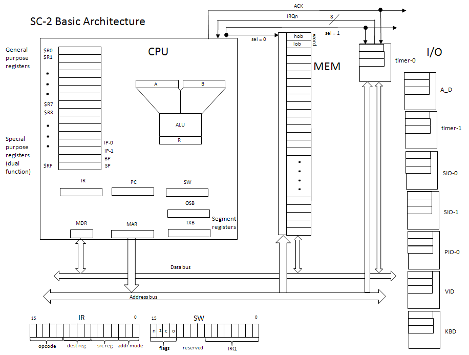
The SC-2 provides sixteen 16-bit working registers (register file). All sixteen registers can be used for data but several ($RC - $RF) are dual use (see below). Address space is 64k (216) bytes. A 16-bit word consists of two consecutive bytes with the high order byte (hob) at the lower memory address and the low order byte (lob) at the next memory address (big endian). Instructions are all one word with the singular exception of the LDA instruction which is two words long; the second word is assumed to be a full 16-bit address. However this instruction is essentially a form of load immediate with a 16-bit immediate field.
The SC-2 is a load and store machine with seven addressing modes. In addition data can be loaded or stored as single bytes or as words. The addressing modes for load and store are:
Computation instructions are strictly register-register. The SC-2 uses a two-address instruction format. The first register designated in the operand field is one operand (for binary operations) and also the destination register for the result. The second register is the second operand. It's contents remains unchanged by the operation, only the destination register is changed.
Control instructions provide for local branching (immediate, using a PC-relative address), long branching (using register-relative addressing), conditional branching on condition code flags (n=negative, z=zero, c=carry out, and o=overflow), subroutine calls, which preserve the return address on the stack (both calls use register-based addressing and one version includes jumping on condition codes), a return from a subroutine, which restores the return address to the PC, a trap call for requesting OS services, and a return from interrupt, which is used to write interrupt service routines.
Below are the details of the architecture that are needed by the programmer. Not all registers are accessible programmatically except through side effects. For example, the PC can be changed by a branch or subroutine call and return, but there is no direct load or store. Similarly the status word register (SW) is changed by state requirements (e.g. an ALU operation) and its contents impact program control, but it cannot be accessed directly by the program for direct examination.
The information given below can be used to write a computer simulation of the SC-2. Instructions, their formats, operand requirements, etc. are given in this specification.
Registers:
	General Purpose:

	$R0 - $RF  16, 16-bit registers

	Special Purpose Registers (as indicated)
	$RC == IP-0	index of source data when loading from data using index mode
	$RD == IP-1	index of destination memory when storing data using index mode
	$RE == BP	base pointer for base-relative mode
	$RF == SP	stack pointer (system) for push and pop operations.

	CPU Registers (not accessible directly by programmer)
	PC  Program counter
	IR  Instruction Register
	SW  Status Word
		Condition Codes: [bF..bC]
			N : negative
			Z : zero
			C : carry out
			O : overflow
		Interrupt Request Lines: [b7..b0]
		Reserved: [bB..b8]

			 F E D C B A 9 8 7 6 5 4 3 2 1 0
			[ | | | | | | | | | | | | | | | ]
			 N Z C O|reserve|  IRQ lines    |

	Segment Registers (for executive/kernel mode code if used)
	OSB  Operating System Boundary (performing a LDOS instruction sets the boundary for kernel space)
	TXB  TeXt Boundary (all read only memory)

	ALU Registers
	A	operand A
	B	operand B
	R	result


I/O Device Port Numbers
	I/O Devices and IRQs
		0 Timer 0 is PIT0
		1 A/D converter is ADC
		2 Timer 1 is PIT1
		3 Serial (COMM1) is SIO1
		4 Serial (COMM2) is SIO2
		5 Parallel is PIO0
		6 Video display is VID
		7 Keyboard is KBD

	Register Port Numbers
	PIT0 = 0x00
		counter register: PIT0 + 0
		timer status:     PIT0 + 1
		time int ctrl:    PIT0 + 2

	ADC = 0x08
		ADC ctrl:         ADC + 0
		ADC status:       ADC + 1
		ADC data:         ADC + 2
		ADC channel:      ADC + 3

	PIT1 = 0x10
		counter register: PIT1 + 0
		timer status:     PIT1 + 1
		time int ctrl:    PIT1 + 2

	SIO1 = 0x18
		register details to be determined

	SIO2 = 0x20
		register details to be determined

	PIO0 = 0x28
		status:           PIO0 + 0
		ctrl:             PIO0 + 1
		data:             PIO0 + 2
		others

	VID = 0x30
		status:           VID + 0
		ctrl:             VID + 1
		data:             VID + 2

	KBD = 0x38
		status:           KBD + 0	// bit 0 is the character available flag, a 1 means it is
									// reading the register clears this bit for the next char
		ctrl:             KBD + 1
		data0:            KBD + 2
		data1:            KBD + 3    // this extra data port allows for use of extended ASCII
									// and special character keyboards - not used in this problem

Interrupt Vector Table
	Fixed address: 0x2100
	Device Map
		0 = 0x2100
		1 = 0x2102
		2 = 0x2104
		3 = 0x2106
		4 = 0x2108
		5 = 0x2110
		6 = 0x2112
		7 = 0x2114

Example I/O device interfaces
	Polling method

	Input from a keyboard device -

	GETINPUT	LDI		$R0, #0			; clear R0
				IN		$R1. #38		; get status register
				AND		$R1, $R2		; R2 = 0x0001 mask
				BRz		GETINPUT		; go back and check again
				IN		$R0, #3A		; get char from data register

	Output to video display

	; assumes character to output is in $R0

	SENDOUTPUT	IN		$R1, #30		; get video status register - bit 0 is clear to send
				AND		$R1, $R2		; check clear to send bit, 0 means it is clear
				BRp		SENDOUTPUT		; 1 & 1 = 1 so not clear
				OUT		$R0, #32		; send data to data register for printing
The following conventions apply to interpretation of the instruction set architecture:
Data Movement
The LC-2 is a strictly load and store machine. Data can be moved between working registers.
ALU Operations
Data Movement
---------------------------------------------------------------
00001	LDI	$Rd, immed7		// $Rd <- SEXT(immed7)
00001 dddd iiiiiii

00010	LDA	$Rd			// $Rd(hob) <-M[PC]; $Rd(lob) <- M[PC+1]
00010 dddd 0000000 aaaaaaaa aaaaaaaa


00011	LDB	$Rd(lob), $Ra		// $Rd(lob) <- M[$Ra]
00011 dddd aaaa 000			// register mode

00100	LDW	$Rd, $Ra		// $Rd(hob) <- M[$Ra]; $Rd(lob) <- M[$Ra + 1]
00100 dddd aaaa 000			// register mode


00011	LDB	$Rd(lob), %$Ra		// $Rd(lob) <- M[BP + $Ra]
00011 dddd aaaa 001			// base-relative

00100	LDW	$Rd, %$Ra		// $Rd(hob) <- M[BP + $Ra]; $Rd(lob) <- M[BP + $Ra + 1]
00100 dddd aaaa 001			// base-relative

00011	LDB	$Rd&			// $Rd(lob) <- M[IP-0]; IP-0 <- IP-0 + 1
00011 dddd 1100 010			// index, register xC

00100	LDW	$Rd&			// $Rd(hob) <- M[IP-0]; IP-0 <- IP-0 + 1;
00100 dddd 1100 010			// $Rd(lob) <- M[IP-0]; IP-0 <- IP-0 + 1
					// index, register xC


00011	LDB	$Rd, @$Ra		// $Rd(lob) <- M[M[$Ra]]
00011 dddd aaaa 011			// indirect mode

00100	LDW	$Rd, @$Ra		// $Rd(hob) <- M[M[$Ra]]; $Rd(lob) <- M[M[$Ra + 1]]
00100 dddd aaaa	011			// indirect mode

00100	MOV	$Rd, $Rs		// $Rd <- ($Rs)
00100 dddd ssss 100			// register to register move

00101	STB	$Rs, $Ra		// M[$Ra] <- ($Rs(lob))
00101 ssss aaaa 000

00110	STW	$Rs, $Ra		// M[$Ra] <- ($Rs(hob)); M[$Ra + 1] <- ($Rs(lob))
00110 ssss aaaa 000

00101	STB	$Rs(lob), %$Ra		// M[BP + $Ra] <- ($Rs(lob))
00101 ssss aaaa 001

00110	STW	$Rs, %$Ra		// M[BP + $Ra] <- ($Rs(hob)); M[BP + $Ra + 1] <- ($Rs(lob))
00110 ssss aaaa 001

00101	STB	$Rs&			// M[IP-1] <- ($Rs(lob)); IP-1 <- IP-1 + 1
00101 ssss 1101 010			// index mode, xD

00110	STW	$Rs&			// M[IP-1] <- ($Rs(hob)); IP-1 <- IP-1 + 1;
							// M[IP-1] <- ($Rs(lob)); IP-1 <- IP-1 + 1
00110 ssss 1101 010			// index mode, xD

00101	STB	$Rs, @$Ra		// M[M[$Ra]] <- ($Rs(lob))
00101 ssss aaaa 011			// indirect mode

00110	STW	$Rs, @$Ra		// M[M[$Ra]] <- ($Rs(hob)); M[M[$Ra + 1]] <- ($Rs(lob))
00110 ssss aaaa 011			// indirect mode

00111	PUSHB	$Rs			// SP <- SP - 1; M[SP] <- ($Rs) //TOS points to last value pushed
00111 ssss 0000 000

00111	POPB	$Rd			// $Rd(lob) <- M[SP]; SP <- SP + 1
00111 dddd 0000 001

00111	PUSHW	$Rs			// SP <- SP - 1; M[SP] <- ($Rs)(lob); // preserve big endian
					// SP <- SP - 1; M[SP] <- ($Rs)(hob)
00111 ssss 0000 010

00111	POPW	$Rd			// $Rd(hob) <- M[SP]; SP <- SP + 1;
00111 dddd 0000 011			// $Rd(lob) <- M[SP]; SP <- SP + 1


ALU
---------------------------------------------------------------

01001	ADD	$Rd, $Rs		// $Rd <- ($Rd) + ($Rs)
01001 dddd ssss 000

01001	SUB	$Rd, $Rs		// $Rd <- ($Rd) - ($Rs)
01001 dddd ssss 001

01001	MUL	$Ro1, $Ro2		// $R8 <- (($Ro1) * ($Ro2))(how);
							// $R9 <- (($Ro1) * ($Ro2))(low)
01001 oooo oooo 010

01001	DIV	$Ro1, $Ro2		// $R8 <- (($Ro1) / ($Ro2)) integer division
							// $R9 <- (($Ro1) % ($Ro2)) integer modulo - remainder
01001 oooo oooo 011

01001	AND	$Rd, $Rs		// $Rd <- ($Rd) & ($Rs)
01001 dddd ssss 100

01001	OR	$Rd, $Rs		// $Rd <- ($Rd) | ($Rs)
01001 dddd ssss 101

01001	XOR	$Rd, $Rs		// $Rd <- ($Rd) ^ ($Rs)
01001 dddd ssss 110

01001	NOT	$Rd				// $Rd <- ~($Rd)
01001 dddd 0000 111

01000	SHL	$Rd, $Rs		// $Rd <- ($Rs) / 2
01000 dddd ssss 000

01010	SHR	$Rd, $Rs		// $Rd <- ($Rs) * 2
01010 dddd ssss 000

[What other ALU operations would make life easier for compilier writers?]

Control
---------------------------------------------------------------

10000	BR	immed11			// PC <- (PC) + SEXT(immed11) - local branch
10000 iiiiiiiiiii

10001	BR	$Rr			// PC <- ($Rr)
10001 rrrr 0000000

10010	BRc	immed9
10010 iiiiiiiii cc
	BRn	00
	BRz	01
	BRc	10
	BRo	11			// overflow = 1

10011	BRc	$Rr
10011 rrrr 00000 cc
	BRn	00
	BRz	01
	BRc	10
	BRo	11			// overflow = 1


10100	JSR	$Rr			// PUSHW(PC); PC <- ($Rr)
10100 rrrr 0000000

10101	JSRc	$Rr			// IF(c == 1) PUSHW(PC); PC <- ($Rr)
10101 rrrr 00000 cc
	JSRn	00
	JSRz	01
	JSRc	10
	JSRo	11

10110	TRAP	vect6			// PUSHW(PC); PUSHW(SW); PC <- (IVT) + SEXT(vect6)
10110 vvvvvv 00000

10111	RET				// PC <- POPW
10111 0000000000 0

10111	RETI				// SW <- POPW; PC <- POPW
10111 0000000000 1


Supervisor Mode Instructions

I/O
---------------------------------------------------------------

11000	IN	$Rd, PORT6		// $Rd(lob) <- IOMAP[PORT6]
11000 dddd pppppp 0

11000	OUT	$Rs, PORT6		// IOMAP[PORT6] <- $Rs(lob)
11000 ssss pppppp 1

Miscelaneous
---------------------------------------------------------------
11001	EI	IRQ8			// SW[IRQ] <- IRQ8 | (SW[IRQ]) (sets bits in IRQ field to 1 to enable)
11001 qqqqqqqq 000

11001	DI	IRQ8			// SW[IRQ] <- IRQ8 & (SW[IRQ]) (sets bits in IRQ field to 0 to disable)
11001 qqqqqqqq 001

11010	HALT				// RB <- 0 (run bit set to zero to stop clock, requires reset to start)
11010 00000000000

11011	NOP				// no operation
11011 00000000000

11100	LDOS	immed11			// OSB <- SEXT(immed11) + (PC) (loads executive mode address boundary)
11100 iiiiiiiiiii			// used to set the executive mode address limit for protecting kernel

11101	LDRO	immed11			// TXB <- SEXT(immed11) + (PC) (loads text address boundry register)
11101 iiiiiiiiiii			// used to keep programs from attempting to write to text or const mem