Insect Flight Research
Abstract
According to the laws of quasi steady-state aerodynamics, insects cannot produce enough lift pressure to fly. The mechanism whereby they achieve flight must involve unsteady flows interacting with the dynamically changing wing surfaces. Quantitative experimental data on this issue is not currently available. We have recently invented a new flow visualization technique, luminescent barometry. We will apply this technique to measuring the time dependent surface lift pressure produced by a bumblebee in flight.
Introduction and Rationale
Insects represent some of the most versatile and maneuverable of all flying machines. Many of them can hover, turn in their own length, decelerate rapidly, role over, loop, and even land upside down on a ceiling. Yet insects cannot fly, at least according to the conventional laws of aerodynamics which rely on quasi steady-state approximations. Clearly, the extra lift required must be generated from the complex (unsteady) flapping motions generated during the wing-beat cycle. Until recently, the exact nature of this extra source of lift remained a mystery.
In three remarkable papers (1-3), Ellington and colleagues have provided insight into the high-lift mechanism used by the hawkmoth, Manduca sexta. These researchers obtained details of the flow around the wings and the overall wake structure by use of conventional flow visualization techniques (carefully placed smoke rakes and stereophotography). Both tethered insects and a hydrodynamically scaled dynamic model were studied. Observations of the insect indicated the presence of a leading edge vortex and highly three-dimensional flow pattern. To further investigate this intriguing discovery, a scaled up robotic insect was constructed and subject to more exacting flow visualization. In this system, further evidence was obtained for a leading edge vortex generated on the downstroke, which moreover was shown to be associated with a strong axial circulation. In addition, the axial vortex was connected to a large tangled tip vortex, extending back to a combined stopping and starting vortex from pronation. Similar experiments have been carried out by Dickinson (4) on fruitflies.
The above works are admirable for the new insights they provide for insect flight, and they encourage further study. For example, the conditions for optimizing vortex stability are at present unknown. In addition, such questions as what is truly the maximum angle of attack and how does the angle of attack vary during the stroke remain to be answered. Also, flow techniques are largely qualitative in nature. Thus, calculations of the mean lift force (2) and span-wise lift force (3) generated by the vortex are highly speculative. Clearly, quantitative studies of the lift force generated as a function of position on the wing surface would be of great value, especially if they could be generated at arbitrary positions of the wing during its wing-beat cycle.
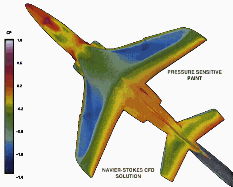
Some years ago, the author of this proposal, together with Professor Martin Gouterman and his students, invented luminescent barometry (5, 6). This technique provides a flexible and relatively inexpensive method and apparatus for continuous pressure mapping of aerodynamic surfaces. It is based on the use of a luminescent paint which consists of a phosphorescent compound, a platinum porphyrin dissolved in an oxygen permeable polymer. When the surface to be studied is coated with the paint and illuminated with ultraviolet light, it is observed to give a beautiful red luminescence. The intensity of the emitted light is found to be proportional to the inverse of the pressure at the surface because the air contains a constant fraction of oxygen independent of the total pressure. Luminescent images are captured with a CCD camera with computer interface. Calibration is accomplished by obtaining a reference image with the wind tunnel fans off. Compared to conventional pressure tap methods, luminescent barometry does not require drilling holes in the surface, provides a much faster response and maps the pressure over the entire surface. Over the past decade, this technique has been refined and used in wind tunnels around the world (7). (see Figure)
Figure Pressure profiles over the plane surface. Left half of plane describes the computational fluid dynamics model results. The right half of the plane reflects the pressures determined by pressure sensitive paint luminescence. Note the excellent agreement between experimental and theoretical results. Adapted from a presentation (7) by Marvin Sellers, Sverdrup Technology Group, Arnold AFB, TN.
It is our belief that the technique of luminescent barometry could be profitably applied to the problem of insect flight. Our desire to carry out such studies has been given impetus by recent advances in computational fluid dynamics and computer power that make possible simulations of unsteady three dimensional flows interacting with moving boundaries. New computer programs, being developed at the Courant Institute will make possible a level of comparison of theory (8) and experiment that is unprecedented.
However, further thought shows that such an application of luminescent barometry is not to be undertaken lightly. Clearly, working with insects will require some knowledge of their physiology. A collaborator with this expertise should be sought. In addition, insect wings cannot simply be painted. The present coatings will load the wings far too much and render them far too stiff. Finally, if theory and experiment are to be quantitatively compared, then it will be most helpful to have the collaboration of a computational fluid dynamicist.
B. Objectives
The overall goal of this proposal is to develop methodology, chemistry and instrumentation suitable for making dynamical measurements of the surface pressure of insect wings during flight. As an experimental subject, we will begin with the bumble bee, Bombus locorum. This insect has transparent wings and the wing-beat frequency is sufficiently high to generate observable pressure gradients. In order to accomplish the above goal, the following tasks must be accomplished:
C. Procedure
(1) Attaching Oxygen Probes to the Surface. Since the wings are made of chitin, and therefore terminated on the surface with hydroxide groups, we may be able to use conventional silane chemistry to attach the platinum porphyrin groups to the surface. Such molecules are available for reasonable cost from Porphyrin Products, Inc. Alternatively, we can use the fact that the wings are coated with a thin (one micrometer) layer of hydrocarbon. We may be able to directly dissolve the oxygen probes in this material. A third possibility is to remove the hydrocarbon layer and replace it with a custom porphyrin-containing hydrophobic layer.
We will begin our coating experiments with detached wings. These will be tested for response characteristics using instrumentation devised for testing the conventional pressure sensitive paints. Once suitable candidates are discovered, we will evaluate them on live insects.
(2) Tethering the Insects. We hope to develop a probe application technique that allows the insect to fly as well as it did before applying the probes. Next , with the assistance of our collaborators in Zoology, we will evaluate technology for tethering the insects. For these preliminary studies we will judge the success of our tethering methods by the wing beat frequency. Methods that alter this parameter by more than ten per cent will be rejected.
Another problem is that pulsed light sources may alter insect behavior. We will be careful to monitor the wing beat cycle using different rates of pulsing, different pulse durations and finally with different pulse energies.
(3) Instrumentation. Obviously, we must be able to capture blur-free images of the insects at multiple positions of their wings during the wing-beat cycle. While this is in principle possible with steady-state light sources using the CCD camera shutter, in practice, we will need to produce images as bright as possible. Thus, we propose to use a xenon flash lamp in conjunction with camera shuttering to yield the most intense phosphorescence images possible.
A major difficulty will be in synchronizing the wing beat with the camera and pulsed light source. We propose to use a microphone to obtain an audio waveform from the wings and trigger the camera at a chosen phase of the waveform. This will coincide with a specific wing position.
In an experiment on the pressure gradients on the surface of a propeller powered by an electric motor equipped with a shaft encoder, we have managed to synchronize the motion of the propeller and the firing of the flashlamp. The image of the propeller is sharp and appears to remain still in space. Next we will attempt to synchronize the propeller with sound from a microphone.
(4) Experiments. With accomplishment of the above, we will be ready to perform experiments. Phosphorescent probes will be attached to the upper surface of live bumblebees and they will be tethered. The system will be equipped with a pedestal so the bees can be rested at intervals. Data will be retained for images taken when the bees are operating within 10% of the normal wing-beat frequency. We anticipate that the pressure changes will be small. Thus we will record many images at the same position in the wing-beat cycle and co-add them. Hopefully, the position of the wings may be reproducible from cycle to cycle. If there are irreproducibilities, we will superimpose the images by coordinate mapping. We have already developed such software for another image processing application.
If the experiments are successful, we will have a pressure map of the wing surface throughout the wing-beat cycle. This data can be integrated in space to give the integrated lift as a function of time. Then such data can be integrated in time to give the average lift. If the data show that the average lift force is greater than the weight of the bee, we can have a modicum of confidence in the data. In addition, the results can be compared with predictions from various theories of insect flight. These will range from simple calculations of the mean lift force for the down stroke as per Ellington (2) to estimates of the lift force and circulation (3) to more sophisticated two-dimensional unsteady flow calculations (8), and finally to the ultimate of three dimensional unsteady flows interacting with dynamically altering boundaries. .
E. The Research Team
The study of insect flight represents an ideal project for an interdisciplinary team. Fortunately, Professor Tom Daniels of the Zoology Department has agreed to collaborate with us. He has a group of people studying the flight mechanism of the hawkmoth. He will provide help with the insect physiology and conventional wind tunnel measurements.
In addition, we have secured the assistance of Dr. Johnathan Wettlaufer of the Applied Physics Laboratory, who is also Adjunct Associate Professor of Physics. He has agreed to help us with the aerodynamic simulations and data analysis. Dr. Wettlaufer, in turn, has connections with Professor S. Childress at the Courant Institute of Applied Mathematics at New York University. Dr. Childress is a leading authority on the aerodynamics of insect flight.
This research team has just been awarded a three-year grant from the National Science Foundation. The grant has support for two graduate students and one post-doctoral student.
F. Contact Us
|
Name |
Office |
Phone |
|
|
Professor James B. Callis |
Bagley 204A |
3-1208 |
callis@cpac.washington.edu |
|
Professor Thomas L. Daniel |
Kinkaid 462 |
3-1659 |
danielt@u.washington.edu |
|
Professor John S. Wettlaufer |
Henderson 601 |
3-7224 |
wett@apl.washington.edu |
References